12AX7 Pre-amp build
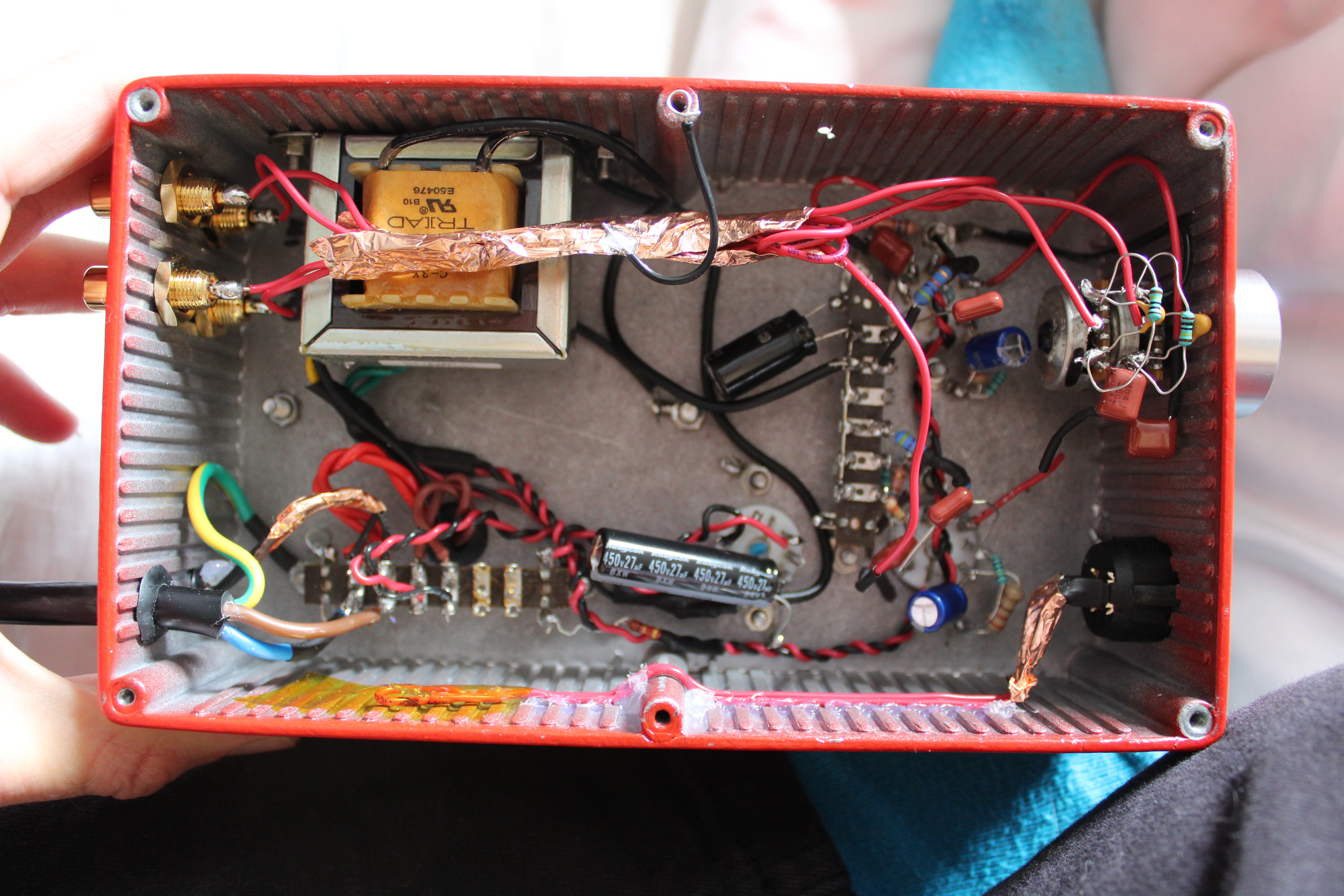
Ever since I restored my Leak Stereo 20 I've been wanting to use my turntable with it. In response to that I tried to find a small preamplifier but was disappointed when I saw the price of them considering they effectively just contain an opamp and some capacitors. I decided it would be much nicer to use some tubes anyway but as a result I ended up spending quite a bit more than if I'd just gone with the "cheap" pre made preamp. Anyway! No digital components! Here are some photos of the end result, and then we will go into some of the decision making.

Parts
I did not keep track of all the parts I ended up using. I suspect going back and trying to find all the orders will be very time consuming - so I'm not going to do that. A few key components though…
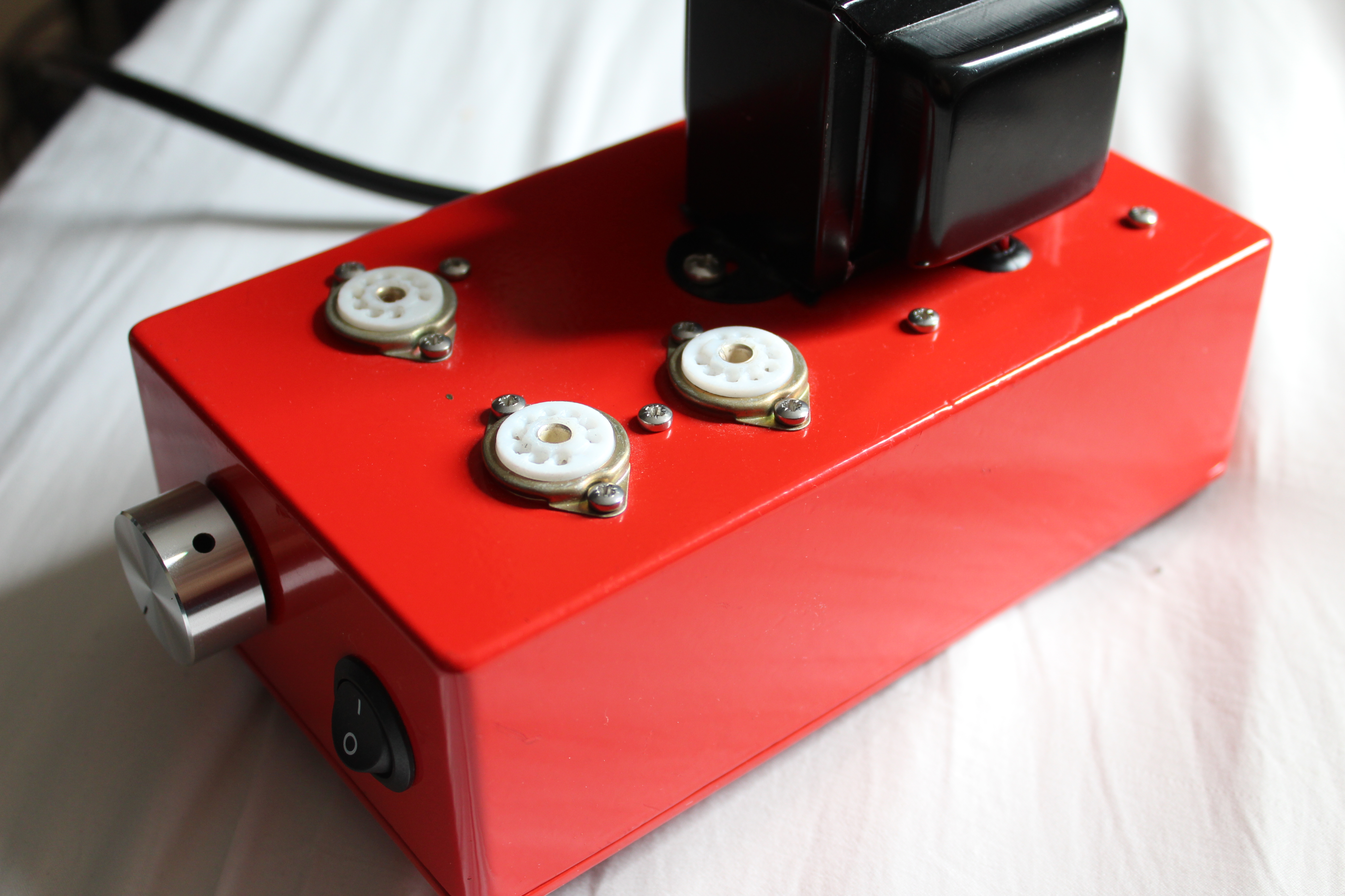
Enclosure
The enclosure is aluminium, pre-finished red, having dimensions 61x112x192mm and is available from Farnell with the part number RTM5006/16-RED. The enclosure cost £17.20.
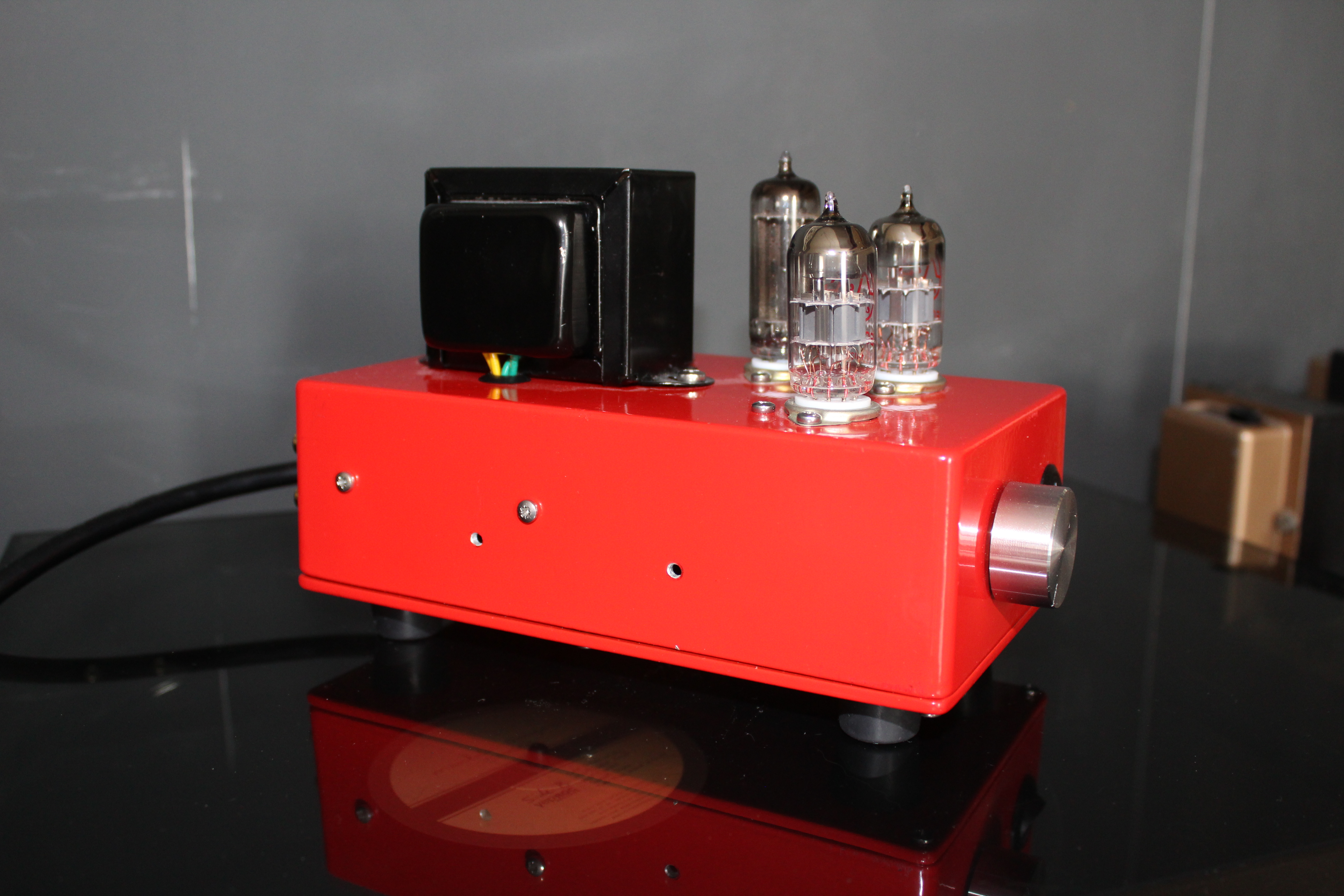
Power transformer
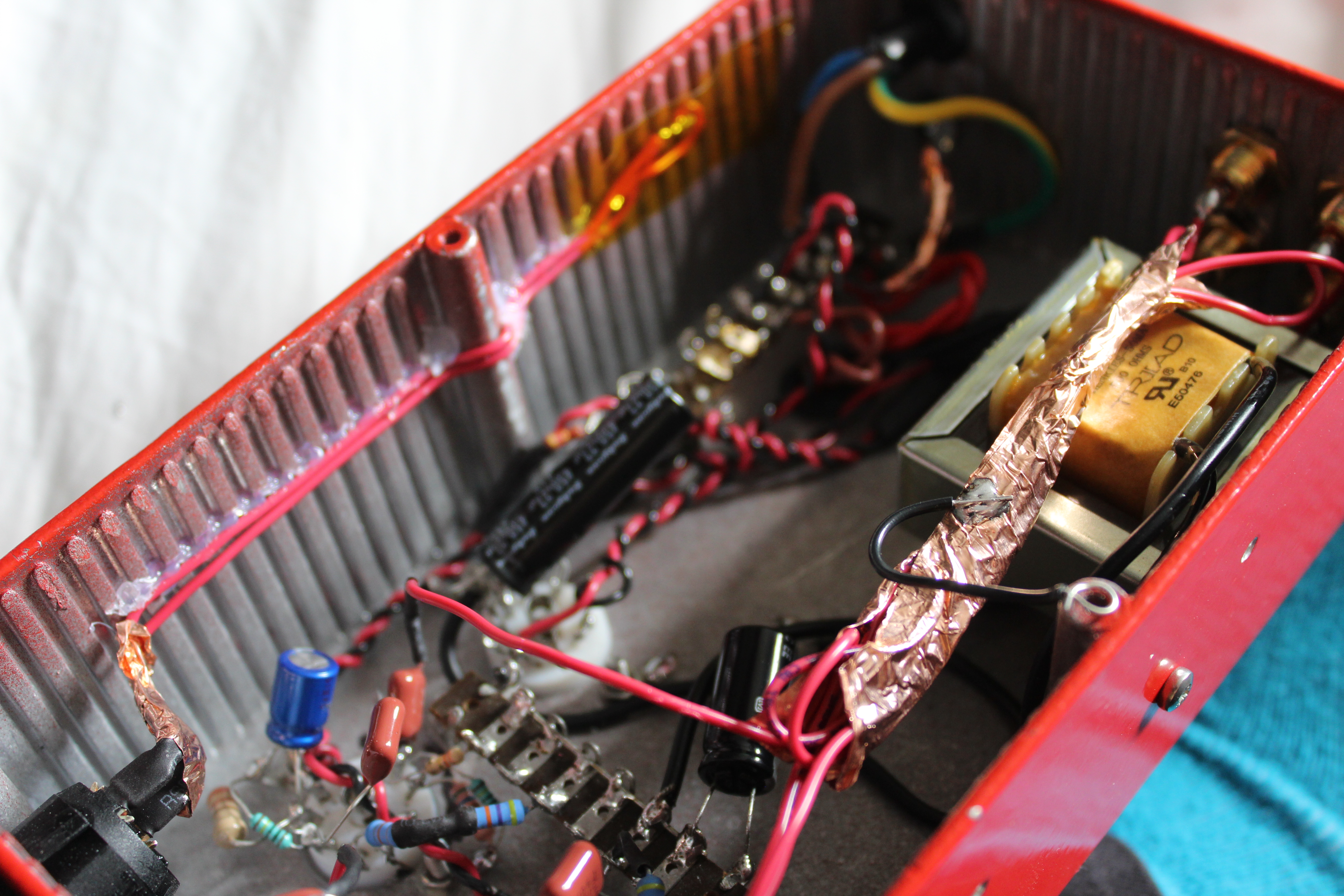
The power transformer was purchased from AliExpress (link here) and cost £14.50. It has a centre tapped 200-0-200 winding, a 6.3V winding and an 8V winding. This was not the best choice because the heaters for the tubes I chose draw too much current from the 6.3V winding, so I ended up powering the rectifier tube off the 8V winding with a dropper resistor. The input voltage is also supposed to be 220V - a little on the low side for the UK. I found I needed to use a 1 ohm dropper resistor on the 6.3V windings too.
Tubes (… and the choke)
The rectifier tube is a Mullard EZ80. An EZ81 might be a better choice but it seems to be surviving. I purchased this tube second hand off eBay for £8. Most schematics for the EZ80 do not include the use of a choke to filter the rectified AC. I found this was very necessary as the rectifier is limited to 50uF of filtering (due to the inrush current). The choke is 10H 500ohm, supplied by Farnell but made by Triad and has the part number C-3X. The choke was an afterthought and resulted in me needing to move some things around (hence a couple of unused extra holes on the side).
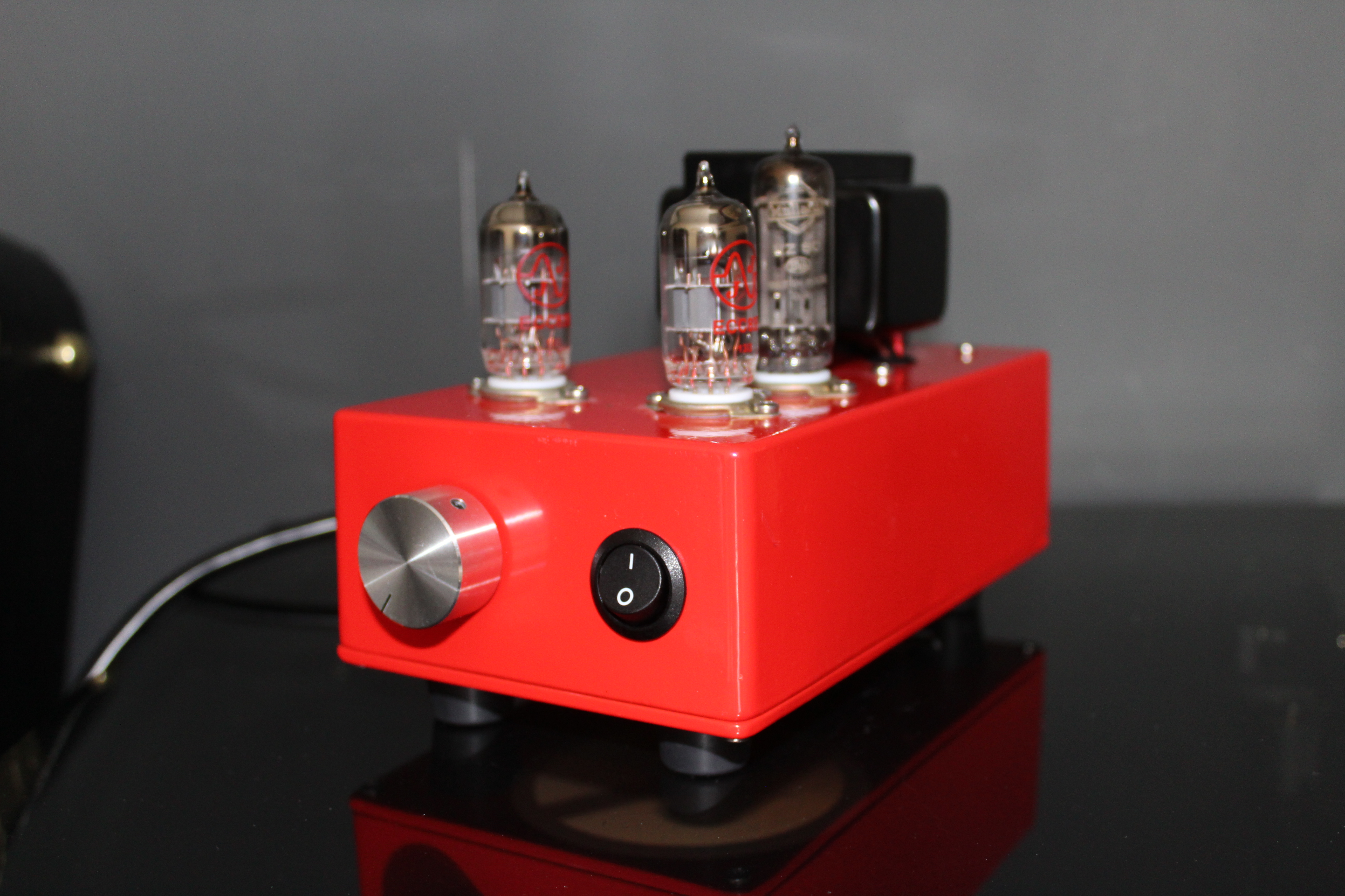
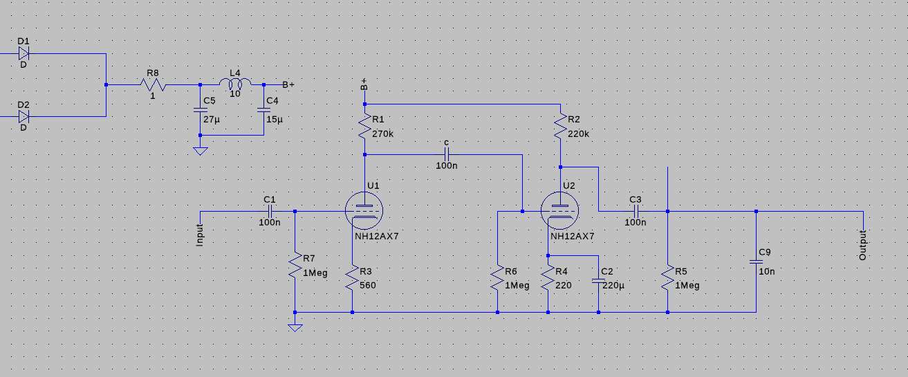
For the amplification, I am using two 12AX7 tubes, manufactured by JJ Tubes but bought from a local guitar store. They are each wired up to provide two stages of amplification. I chose the capacitor and resistor values for this by modelling the amplifier in LTSpice, which allows you to use a wav file as input and output. With an input of around 4mV the pre-amplifier will deliver at least 2V.
The tube sockets and terminal strips came from J. Birkett, based in Lincoln but I bought these parts from him at Newark ham radio rally. He has lots of good quality NOS parts!
Other Components
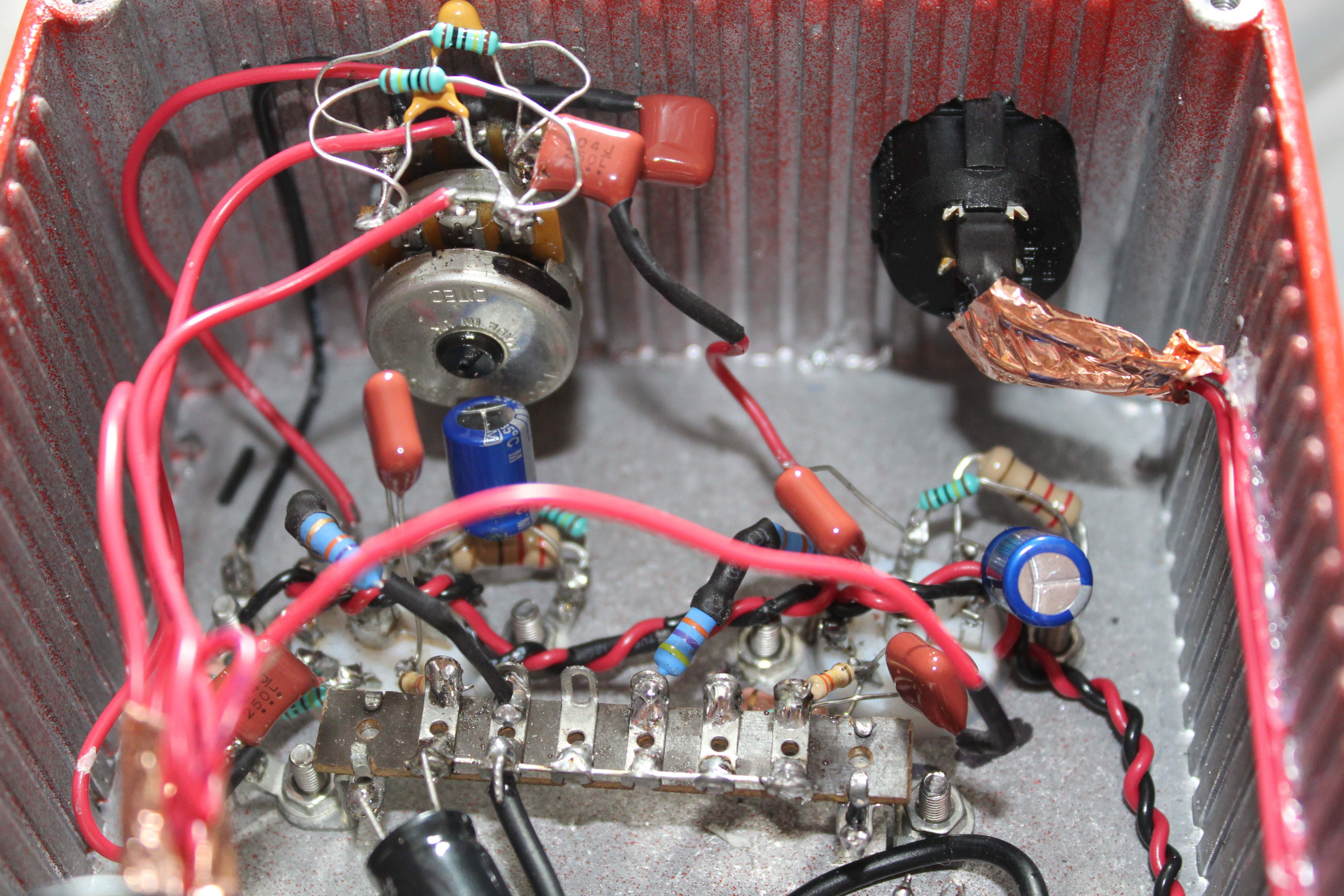
I added a small neon tube to the back with a small dropper resistor, just as a power indicator. The volume control is a 50K logarithmic pot with a machined aluminium dial, which came from eBay. The power cord came from my local Screwfix - I bought a whole reel of it.
Notes
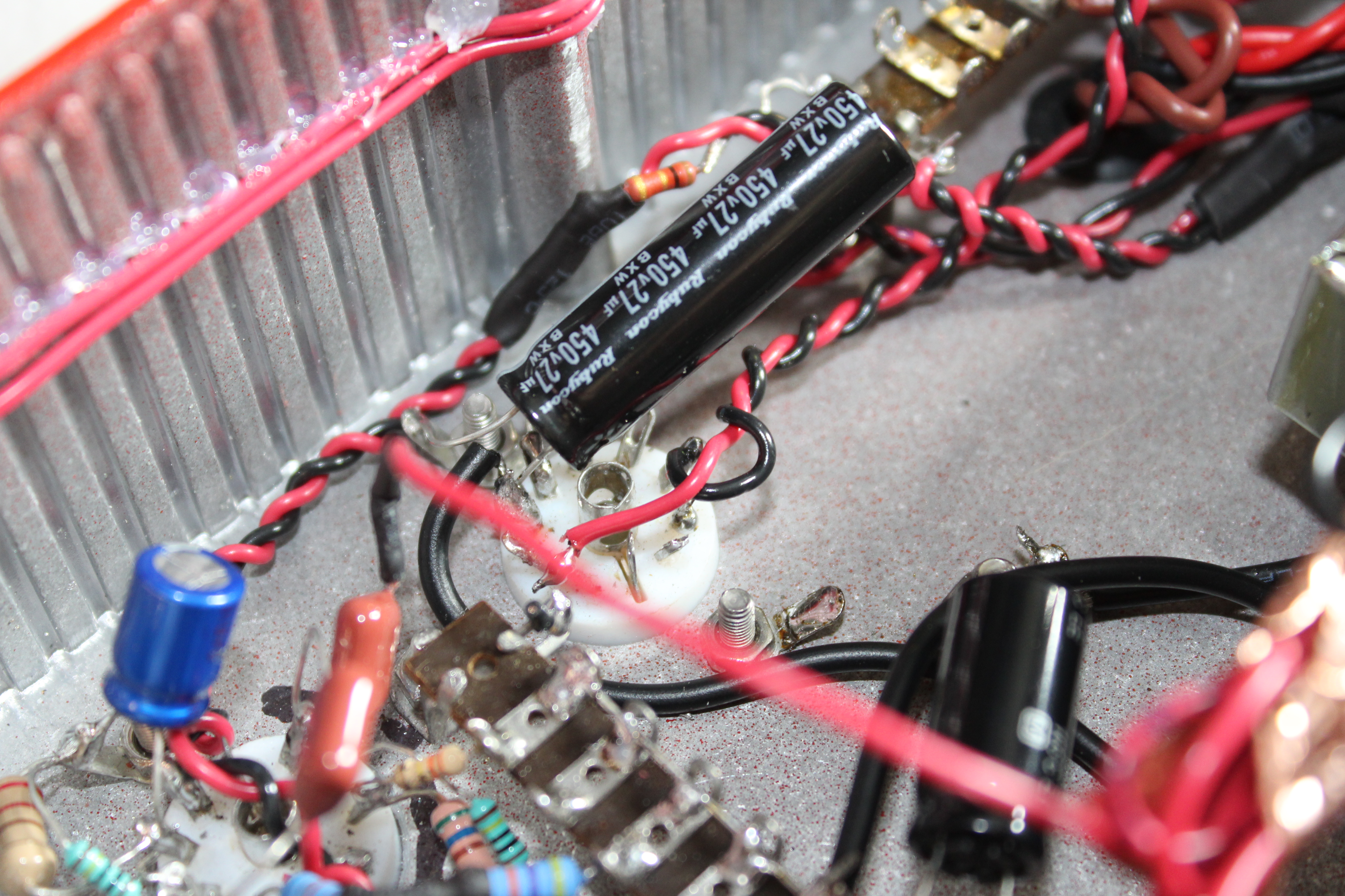
The amplifier performs very well. The noise was gradually reduced, first by installing the 10H choke, then improving the heater wiring and then finally by disconnecting the power switch. Running the mains AC lines through the amplifier was a bad idea. I should have put the switch on the back. The switch will remain there unless I can think of something more useful to have on the front. The hum is now very quiet. Contrary to some comments, passing the input and output lines across the choke really is not a big deal. In fact, it's one of the quietest spots in the amplifier - just wave your scope probe around and see for yourself :)
I really learnt the importance of neat and tightly wound heater windings. You can see these in the photos below.

I found that the amplifier was a little high on treble so added a 10nF capacitor across the volume controls (essentially from the tube output to ground). This really improved the sound. The value was chosen by trying a few different values in LTspice.

N.B. I've since improved the wiring even further and tidied things up a bit, which again reduced in a slight reduction in hum.
Tooling
This was the first time I've ever done anything with an aluminium enclosure, so I was a little apprehensive about drilling into the chassis. Turns out it is actually very easy. I used a punch down tool to make a small indent in the surface and then used a stepped drill bit. This was very handy because I'd already know in advance what size hole I needed, so I could just go up to that point. Initially I started with a masonry drill. Wow… Bad idea. It cuts way too quickly and jams up. I have a small Bosch electric screw driver, which the stepped drill bits fit into nicely. This worked far better. I think the trick is to just take it slow and apply very light pressure.
Schematics
Below is essentially what the schematic looks like. I haven't included things like dropper resistors for heater windings. This only shows one channel. The 1ohm resistor after the rectifier was just to measure current in LTspice.
The End
I will finish off with a video of Grapevine Fires by death cab for cutie.
Future Plans
I consider this project pretty much finished. I found that the gain between the two 12AX7 tubes is a little off. One channel is louder than the other. I may buy a few 12AX7 tubes and switch them until I find a pair I'm happy with. I think I should also replace the pot. The two wipers don't seem to track each other properly, so the resistance on one is always higher. I've put the tubes in so that the louder tube is on the high resistance wiper, so they are somewhat even now, but this is a dirty hack…
Update - Further Hum Reduction
I came across this excellent page by "The Valve Wizard" which gives some very useful tips to reduce noise, particularly with high gain tubes such as the 12AX7. The most useful tip was to create an artificial centre tap by connecting both sides of the heater winding to ground via 100 ohm resistors. This pulls either side of the heater winding to have an RMS voltage of ~3.15V each. Because both sides have equal but opposite fields, they are better able to cancel each other out when using twisted wires. Excellent! I observed a very significant reduction of hum audibly, and around 10dB or more according to the FFT of my scope.
Update - A hand drawn schematic
This one is a little more accurate and shows more detail about the power supply etc. Click through for a full sized version.

Related posts:
Wanting to leave a comment?
Comments and feedback are welcome by email (aaron@nospam-aaronsplace.co.uk).