RL02 - A Disk Pack of Worms (Work in Progress)

It's the Christmas break, which means I'm not thinking about work and have energy to do something interesting. The weather is also quite terrible, so I am not cycling much at the moment. I've been ignoring my RL02 drives for over 2.5 years at this point, last posting about this in March 2018, where I begin to suspect that I may have found the problem with my RL02 drives. Unsurprisingly, I never actually fixed it, nor did I confirm what the actual problem was. In an attempt to rectify this ignorance and to fix the problem, I will be carefully going through all of Chapter 3 of the Technical Description manual. I'd already performed some of these in my previous post, but will be repeating them for the sake of sanity.
This post will be broken up into several parts. I will begin by
giving an overview of the problem, followed by describing the drive
components. This will ensure I have actually read the relevant parts of
the manual, and understand what everything does. I'll then go through
the checks described in Chapter 3, while making the corrections.
Finally, before starting, I should mention that this post will be long.
As bnl used to constantly remind me, if you are going to
fix something, understand it first and read the manual back to back. So,
if you are interested in RL02 drives, or want to try and fix your own, I
hope you find this post helpful. However, the intended reader is myself,
and it's really just a way to keep track of the alignment procedures and
to force myself to understand what's going on.
For your convenience,
- The Problem
- Drive Components
- Checks, Adjustments and Alignments
- Time for some thinking…
- Understanding the Tachometer
- Monitoring Position Test Point As Heads Attempt to Load
- The Grounding Button
- The Grounding Button (Part 2)
- Investigating the 'Tachometer AC Noise Pickup' problem
- Most Likely a Pair of Bad Cartridges?
- BC80J-20 Cable vs a Ribbon Cable
- The State ROM
- Lock On
- Lock On (Follow Up)
- Removing the bearings
- Checks, Adjustments and Alignments - Continued
- Notes
- Formatting RL02 Cartridges
- Performing Alignments is Stressful
- Some Photos from 19th December 2020
- Oscillating Program for Switch-register-less PDP-11
- Position Signal Gain Check - Action 3 (Verify heads produces sinusoidal output)
- Position Signal Gain Check - Action 4 (E4 Pin 4 and Pin 9)
- Tachometer signal with and without LED lighting
I will also try to list the relevant updates since they are (or will be) placed randomly throughout the post.
- 2022-11-18 The Spindle Grounding Button (Part 2)
- 2022-11-26 BC80J-20 Cable vs a Ribbon Cable
- 2022-11-27 The State ROM
- 2022-12-01 Lock-on
- 2022-12-02 Lock On (Follow Up)
- 2022-12-04 Removing the bearings
The Problem
If these drives are going to take up as much space as they do, they
better work! At least, that's what I'm telling myself. I'd probably hold
onto them regardless. Still though, they don't work. I'm mainly focusing
on one specific drive. I consider the other to be a parts unit. So, the
problem… The drive spins up and the heads load. The drive will them
immediately go into FAIL mode. Adding the SKTO jumper
(mentioned later), as well as the position inhibiting jumper (also
mentioned later) will allow this drive to go into READY
state. However, I believe with either of these jumpers installed, the
drive will not respond to commands from the PDP-11. Or, it's in such a
state, that it definitely doesn't work and the PDP-11 is correctly
throwing 'device error' messages.
Drive Components
Let's first try to remind myself of the drive components and what everything does.
The RL02 Cartridge
I think it's important to start with the cartridge, since we need to know the layout of the cylinders and sectors, as well as have an understanding of how data are encoded on the platter.
An RL02 cartridge contains a two sided platter. Each side of the platter has 512 cylinders. Each cylinder has 40 sectors, and each sector is made up of 140 words, each of 16 bits. Only 128 of these words are used for storing actual data.
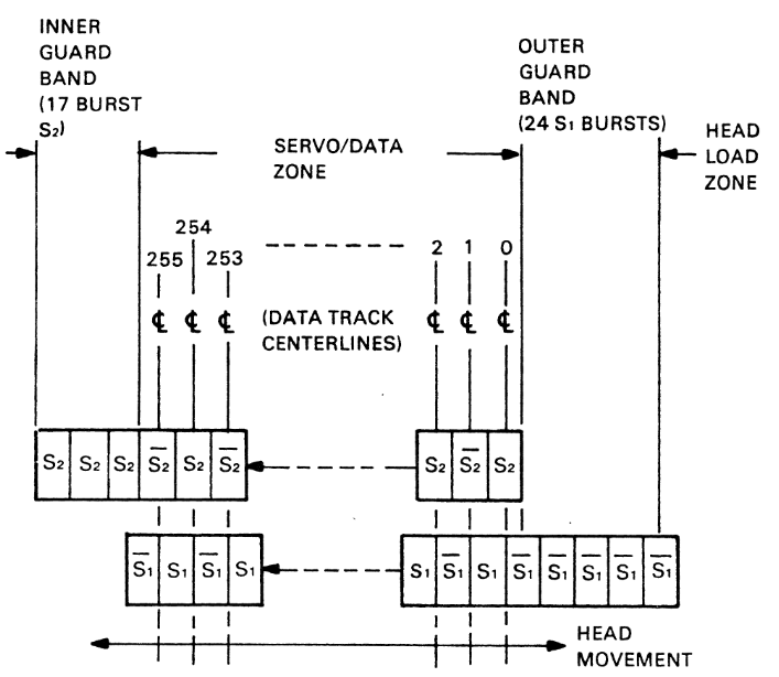
Servo Bursts - The servo bursts are used to locate the tracks on the platter. Unlike many drivers before the RL drives, these are encoded directly along side the data, which avoids the need for a secondary head, and reduces the amount of alignment required. Unfortunately, writing servo bursts was done at factory, and no one has figured out how to replicate that process - so, take care of your cartridges. As the heads move in and out of the cartridge, the servo bursts are counted. This allows the drive to know which track the heads are currently hovering above (or below).
I will not go into detail on how the servo data are encoded, but if you are curious, this is described in the technical manual under Chapter 2. However, what we should know is that that on the most outer and most inner tracks of the platter, there exists a Guard Band. These have only one of the S1 or S2 servo bursts. The outer edge has only S1, and the inner edge has only S2 bursts. This is best explained in the figure to the right. You can presence of S1 and S2 for the data tracks, but guard tracks have only S1 or S2. This information will be helpful while performing alignments later.
Header Preamble - This preamble consists of 3 (16 bit) words. Combined, it makes up 47 zeros, followed by a one, which indicates the start of valid information.
Header - The header contains 3 (16 bit) words, which describes the location of the sector. The first word specifies whether the track is on the upper or lower side surface of the platter, followed by the cylider address (which is between 1 and 512 on the RL02), followed by the sector address (1 to 40). The second word is all zeros for some reason. The third word contains a CRC checksum to verify that the header has been read correctly.
Header Postamble - A single word of 16 bits, containing only zeros. Apparently this is to allow for mechanical slop within drives.
Data Preamble - Consisting of 47 zeros and a single one bit, indicating the start of the data, just like the header preamble.
Data - 128 (16 bit) words, followed by a 16 bit CRC. The CRC is generated and checked by the controller installed in the PDP-11, not by the Drive Logic Module.
Data Postable - Finally, just another string of 16 zeros. This ensures enough time to turn off the write heads, so that the proceeding sector isn't over-written. I suspect this is also true for the header postamble.
Let's finish off our description of the platter with an overview of the encoding used. Data are written to the cartridge using a Modified Frequency Modulation (MFM) technique. Something similar is still used today, and it's necessary because you can't just write a stream of zeros and ones to a magnetic surface. You can only encode state transitions. Under this scheme, a logical one is encoded as a flux reversal, with the peak centered above the bit. It's also worth pointing out that these flux reversals repel each other. The drive controller shifts this state transitions by 15ns if close to another, so that the flux reversal is centred correctly above the bit.
Drive Logic Module (DLM)
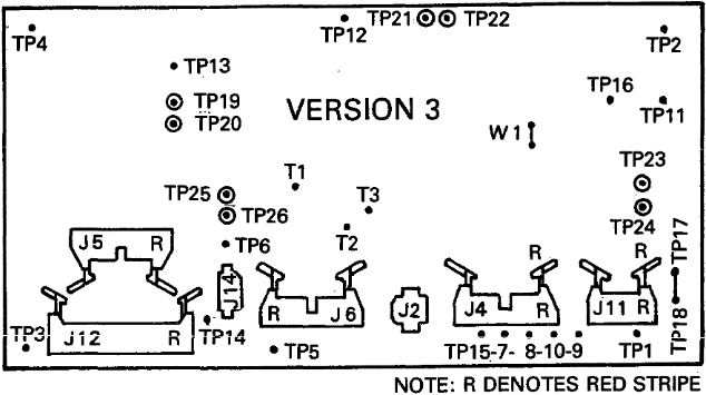
The DLM ties all the components of the drive together. Between the RL01 and RL02 drives, there were three versions of this board. I have version 3 and I know this because my boards have TP21-22 and TP25-26, which the previous versions lack. The purpose of the DLM is to tie all components together. It provides an interface between the storage controller installed in the PDP-11, and the read/write module. There are some important jumpers which we need to take note of, so that we can perform all of the checks described in Chapter 3.
- TP23-24 - Disables Sector Seek Time Out (SKTO) when a jumper is installed. This means the drive will try seek indefinitely until it finds the first servo track.
- TP25-26 - Default Position Signal. The voltage level on the position signal varies depending on the position of the read/write heads. This jumper ignores that, so the drive will think everything is fine. Looking at the schematic on page 59 of the Nov 1979 schematics, this jumper simply pulls the signal down to ground.
- TP21-22 - Forces the drive to use head 1. This is helpful when probing the read/write module, since you can compare signals from either side of the platter.
- TP19-20 - Default cover closed interlock. You'll definitely need this plugged in if you are doing any probing. Otherwise, your finger will get very sore trying to push in the lid button. It's got quite a sturdy spring.
Additionally, there are quite a few test points (the non-jumper kind) which we should be aware of, so we can gain a better understanding of what we are actually doing during the checks, adjustments and alignments described in Chapter 3. If a test point is not listed below, it's either not important to the tests, or does not exist on version 3 of the DLM.
- TP1, TP2, TP3, TP4, TP5, TP6, TP12 - These are all ground lugs. Use whichever is closest to your probe.
- TP8 - Tachometer Output - This voltage on this test point indicates the direction and speed of linear travel of the read/write heads.
- TP14 - Sector Transducer - This provides a pulse at the start of every sector. I believe this is basically hooked up directly to a halls effect sensor.
- TP15 - Position Signal - This test point gives a DC
voltage describing the linear position of the read/write heads. We need
to understand the voltage of this test point properly, since it
describes misalignment between the heads and any given cylinder.
- The DC value will slowly float towards 8V while the heads are
parked. Once this reaches close to 8V, the
READYlamp will turn on. - When the head is over the outer guard band (S1 bursts only), it will
be at it's most negative value of -1.5V. The
READYindicator will be off at this point, since the heads have not found cylinder 0. - The DC value will change to 0V once the heads are located over
cylinder 0. At this point, the
READYlamp will turn on again to indicate that the drive is ready to be used. - As the head moves between cylinders, it will ramp up to 1.5V and then back down to 0V as it positions itself above a cylinder again.
- The DC value will slowly float towards 8V while the heads are
parked. Once this reaches close to 8V, the
Read/Write Module
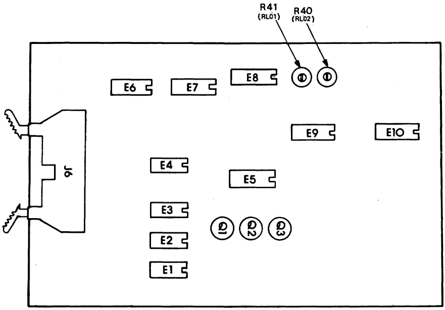
The Read/Write Module (RWM) is responsible for amplifying the signal to and from the read/write heads. It has two potentiometers, but you only need to worry about the one closest to the front of the drive. This varies the amplitude of the signal read by the heads. The module also features two test points, one of which I'm unsure about.
- TP1 - !Data - This test point is not described, but having probed it, it appears to be the inverse of TP2. This is confirmed by checking page 18 of the Nov 1979 schematics, which show TP1 positively referenced and TP2 negatively referenced.
- TP2 - Data - This test point allows you to see the amplified signal from the read/write heads. This signal is broken up into two parts. First, the servo bursts, S1 and S2, followed by a header and then the data. My scope only has enough record length to capture S1 and S2, as well as the beginning of the header.
To be honest, there is not much more to say about this module. On the underside, there are two connectors, which go to the two heads.
DC Servo Module
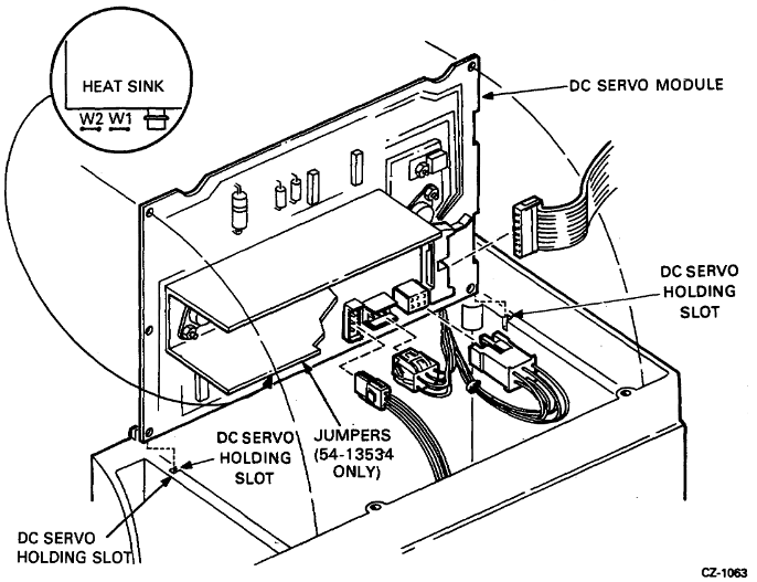
The DC servo module has it's own set of test points, and is responsible for moving the read/write head carriage back and forth. Later, when we check the voltages, they will be done on the test points on this board. The DC servo module is also responsible for position tracking of the heads, which is based on the amplitude of the servo burst data. Misalignment or poorly adjusted read amplitude may cause this signal to vary wildly, which in turn will cause the read/write heads to move in and out, sometimes quite aggressively.
Aside from the voltage test points, there are a two slightly more useful points we should be aware of,
- TP1 - Summing Amplifier - This test point describes how far away the heads are from their target track. This signal is amplified and used to drive the read/write head servo motor.
- TP3 - Servo Current - This test point allows you to sense the current through a 0.2Ω sense resistor, which drives the read/write carriage servo motor.
Other Components
There are of course several other components within the drive. This includes the AC servo control board and the control switches. The latter I don't think we need to worry about at all, although for reference, these bulbs are CM73 (Chicago Miniature) incandescent bulbs, which run on around 14V and take 8mA. You may also find it interesting to know that these bulbs do not switch off when the drive is running, even when they appear to not be illuminated. The drive trickles a small amount of current, invisible through the filter of the button, which helps extend the life of these bulb.
Checks, Adjustments and Alignments
This section might take a while to complete. At the time of starting this post (wow, already 2.5 hours in), I certainly hadn't completed all of the checks. We'll work our way through them one at a time.
Voltage Checks
I've checked these and they were all spot on. Nothing else to say about that!
Sector Transducer Output Check
I think this is the output of the transducer before it is passed through a comparator. I found the voltage of mine to be a little higher than that shown in the figure of the manual, but I think this is fine still.
![]()
![]()
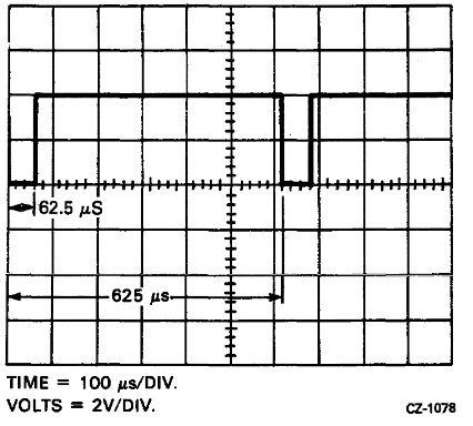
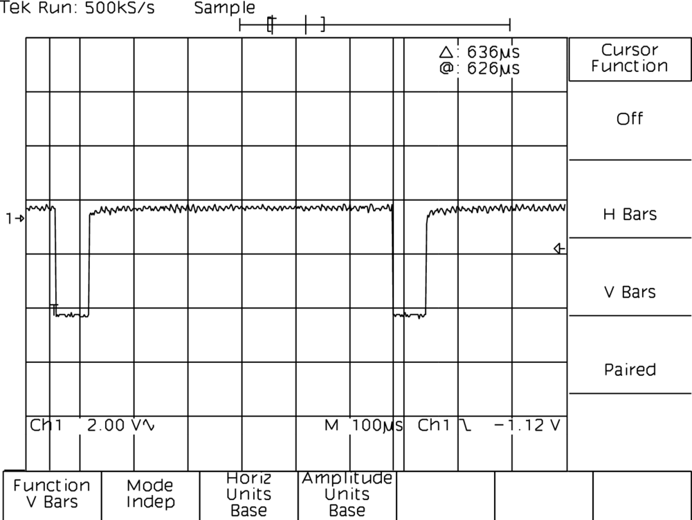
Sector Pulse Timing Check
The main purpose of this test is to ensure that the platter is spinning at the correct speed, and that the sector transducer is outputting a suitable voltage. As we can see below, this was fine. The time between triggering and the cursor (which is a little too far ahead) is 626μS, and should be 625μS. This is completely fine, the allowable range is 594μS to 639μS.
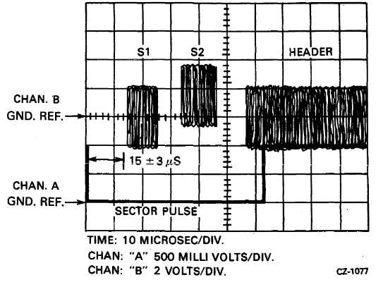
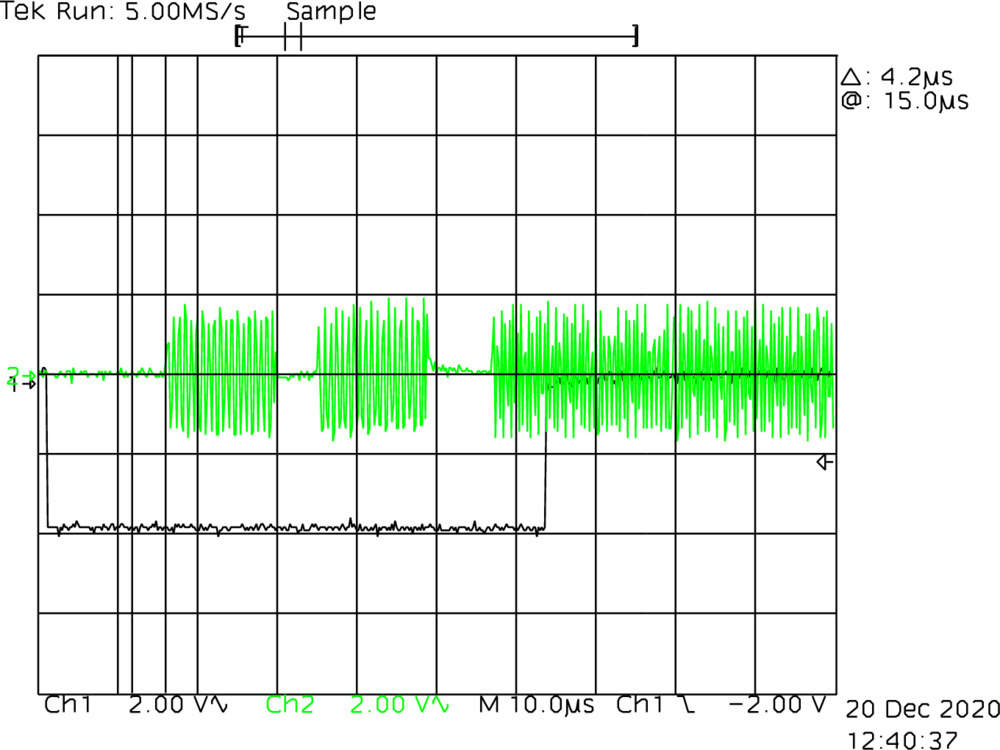
Read Signal Amplitude Check and Adjustment
This is one of the checks I did do in my previous post. However, for the sake of completeness, I repeated it today. Section 3.5 of the technical description manual indicates that the time between a falling edge of the sector pulse and the start of the S1 burst data, should be 15μS +/- 3μS. The main purpose of this test is to ensure that there is a suitable time delay between the sector pulse and the start of servo data. The second purpose is to ensure that the amplitude on the read/write module is set correctly. By doing so, we also verify both heads are reading ok. For me, this checked out, it was pretty much spot on 15μS. It also states that the amplitude of the S1 should be adjusted (using R40 on the read/write module) to be 650mV.
Step 21 of this section indicates that the maximum amplitude of the servo bursts when hovering above/below track 0, is 2.25V. However, I get the same amplitude pretty uniformly across the whole platter, so perhaps the cartridge is just a bit old and tired. I'm not sure if this is actually something to be worried about.
<2020-12-20 Sun 14:38> Today I tried a different cartridge and found that the voltage on the outer guard band is quite a bit higher than that of the inner guard band. This seems like a better cartridge to continue using.
Positioner Radial Alignment
This is a very scary procedure which involves loosening the head assembly, while the heads are hovering over the disk, and nudging it from side to side. The main purpose of this is to ensure that the heads are completely straight, since any deviation would result in a timing difference between the sector pulse and the start of the S1 servo burst. Mine was a little wonky, only 2μS or so, and the allowable range is 3μS. I did the alignment again for practice. The screen dumps I show below are the outer guard band (getting 15μS) and the last track, just before the inner guard band (getting 16μS). From this we can be quite certain that the heads are straight.
The second reason for performing this alignment is to ensure that the heads are not off axis from the outer most part of the track, since this would result in a weak signal and potentially crossover from the neighbouring tracks.
Oh, also, it's worth mentioning that you'll see the amplitude of these signals is weaker on the most inner track than on the outer guard band. This is normal, and I had problems with another cartridge (as mentioned earlier) where the amplitude was uniformly weak, which can lead to overcompensating the amplifier while performing the read signal amplitude adjustment.

Head Alignment
The purpose of this alignment is to reduce the servo tracking time when switching between either side of the platter. At the time of writing this is the least of my worries, but I did make some small adjustments to try and get the S1 burst aligned evenly while switching between head 0 and 1. I didn't capture any screen dumps from the scope of this. This is another very terrifying alignment, where you lose a 3/32th of an inch hex bolt (stupid imperial units), and then slide the head in and out by small amounts, while switching between the two heads.
Spindle Runout Check
There is no alignment involved in this check, it's more about sanity checking. If the spindle is unlevel, the platter will also be unlevel, and this may cause tracking issues. If the spindle is fine but this check fails, the cartridge may also be damaged.
<2020-12-20 Sun 14:59> Didn't end up checking this today, but I did quickly check it yesterday and it appeared to be ok. I had my scope set to 200mV per division and the signal did not drift outside of that. Still, will check again another time!
Position Signal Gain Check
This is a check which I am particular interested in. As the position
signal floats away from 0v, the heads move in or out slightly to
compensate. Having performed all the aforementioned checks and
alignments, the situation is looking perhaps slightly more healthy. In
the original problem section, I mentioned that the drive loads the heads
and then a FAULT lamp comes on unless the sector seek
timeout (SKTO) jumper and position inhibit jumpers are installed. Now,
even without these jumpers, the heads load, but they jitter back and
forth.
The manual for this check states that:
Insufficient amplitude of the position signal could result in the carriage not being able to hold itself on track, resulting in read errors and possible seek errors. Too high an amplitude could result in a jitter which, in turn, emits a vibrating type noise from the carriage that may generate seek timeout errors.
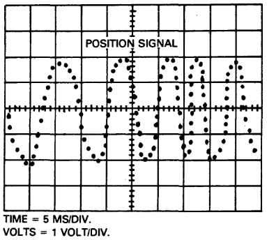
Sound familiar? Yep. So, to do this check, you disconnect the power to the carriage motor and move the heads back and forth while monitoring the oscilloscope. The output should have an amplitude of 3.7 +/- 0.7V, while probing TP15 (Position Signal). If this isn't the case, there are two potential reasons. The first is that the +/- 8V supply rail is out of tolerance, but we've already confirmed this not to be the case. The second can be checked by probing TP2 of the read/write module, as in read signal amplitude check. Zooming in on the signal, we check if it's a smooth sine wave or quite jittery. If the latter, it means the heads are bad, likely due to the azimuth of the heads. Unfortunately, this would not be good, because obtaining new heads will be near impossible now. This needs to be repeated for both heads of the drive.
I've not performed this check yet. Maybe I'm scared that the heads are actually in very bad shape. Although, looking closely at the screen dumps from the positioner radial alignment, they do appear to be reasonable (although very squashed) sinusoidal signals. I instead want to interrupt this check to investigate the DC servo module.
Before we can start this, I realised I should try to gain a better
understanding of how the heads are moved or held in position. The drive
has two modes of operating, velocity mode and position mode. In
velocity mode, the DC servo module keeps track of the
current head position by decoding the information stored in the servo
burst data. To assist with this, the drive also monitors the linear
movement of the heads by way of a tachometer mounted on the read/write
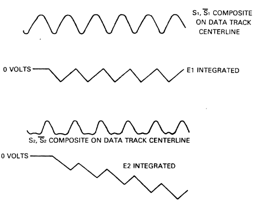
head carriage. The servo bursts are decoded by integrating the S1 servo
burst. When this is perfectly sinusoidal, the heads are perfectly above
the track. The integral of this is made available by a signal line named
E1. A perfect sine wave will result in a saw tooth signal
on E1. The S2 servo bust will not be perfectly sinusoidal
when the heads are correctly located. This is reflected as an imperfect
sawtooth on a signal line named E2. This is best explained
by means of the figure to the right.
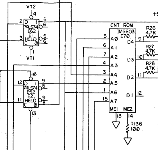
These integral signals, E1 and E2 need to
converted into a binary format. If either E1 or
E2 is a perfect saw tooth, the binary representation of
either binary representation will be a zero. If one is a not a perfect
saw tooth, it will have a binary representation of one. This is done by
means of a flip-flop circuit for each signal line. These binary signals
are then named E1 Held and E2
Held. These four lines are then used to address a count ROM,
along with three bits from the velocity signal and a bit which indicates
the direction of linear read/write head movement. The output from this
ROM is fed into a decoder circuit which decrements the track difference
counter.
If the track difference counter is zero, the drive enters
position mode, which means the read/write heads are
directly over the center of the desired track. As mentioned earlier, in
this state, E1 will have a perfect saw tooth, and the
average of this signal will be zero. This forms the basis of our
position signal. If it's not a perfect saw tooth, the average of this
E1 signal will be moving away from zero, either positively
or negatively, thus representing the error from the desired track. In
order for the drive to be in READY state, the position
signal must be zero for at least 6.5mS.
To recap the current state of the drive: the heads are able to load
onto the cartridge without immediately causing a seek timeout, or a
position error. This means the FAULT lamp remains off.
However, the READY lamp flashes as the heads jitter back
and forth. Monitoring the oscilloscope while hooked up the TP2 of the
read/write module, the S1 servo burst from the outer guard band appears
in time with the READY lamp illuminating. Let's run through
a few ideas about what might cause this, and what we can do to test:
- If the spindle is wobbly, the heads will have a hard time remaining fixed over the track. The check for this is the previous check "Spindle Runout Check" which I sort of glanced over because it appeared fine when I quickly checked it. So Action 1, properly measure the spindle runout.
- Despite distracting myself with details about servo bursts, I should probably return back to purpose of this section: Position Signal Check. Action 2 Check to see if the position signal is within range while moving the heads and make sure it's around 4V peak to peak. If it's not then we should investigate the heads.
- Action 3 Connect back up to TP2 of the read/write
module and zoom in closely on the servo burst. Make sure these are nice
and sinusoidal. If they are not then it really is likely that our heads
are bad.
- <2020-12-20 Sun 23:13> I've checked this and included screen dumps in the notes section towards the bottom of this post. I show two dumps from the S1 servo burst, one much more zoomed than the other. Comparing this to a pure sine wave would suggest that heads are not in great condition, but it's more sinusoidal than the alternative, so I think we'll just have to pretend they are fine and continue.
- The read/write module contains the circuitry to separate out the S1
and S2 servo bursts (See page 18 of Nov
1979 schematics.). These are made available to the Drive Logic
Module via ribbon cable. Action 4 is to probe these
from IC E4 to make sure they look reasonable, and to make sure they are
what I expect. I think they should look like an inverted copy of the S1
and S2 bursts which we saw earlier, but square.
- <2020-12-20 Sun 22:53> I decided to take a look at this tonight and the outputs of pin 4 and pin 9 are shown in the notes below. They are not particularly useful or interesting, and basically as I'd expected.
If everything up to this point looks ok, it may be worth looking into
what happens to the signal on the Drive Logic Module, since here it will
be integrated as E1 and E2 as saw tooth
signals. The average of this is then used to derive the position
signal.
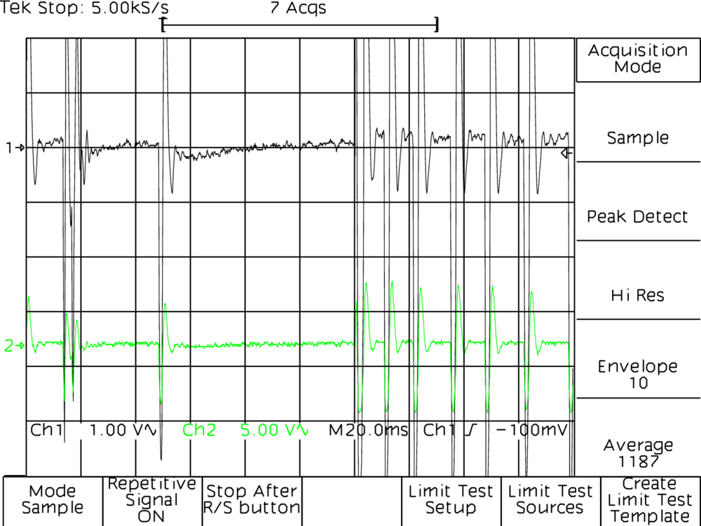
Tachometer AC Noise Pickup Check
This is another very interesting check, since the manual states for this check,
If the noise is excessive, the positioner will have a hard time holding onto a track signal. In this case, the
READYlight may flicker.
To test this we disconnect the power to the carriage so it can't move around, and attach the oscilloscope probe to TP1 of the DC servo module. This test point is the summing amplifier output. The total peak to peak voltage of the signal should be no more than 350mV. If it's higher than this, the DC servo module might have an issue, or the main drive motor is creating a lot of noise and should be replaced.
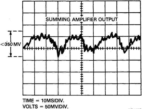
I may need to repeat this test because I carried it out while quite tired. However, the output is quite concerning. There are some very large spikes even though the power to the read/write head servo was disabled - so they should not be moving! The manual says if the signal is out of tolerance, it may be necessary to replace the DC servo module, or the main drive motor. Hmmm. How can I find out if the motor is causing noise?
Time for some thinking…
I feel like we might be onto something here, so perhaps it is worth pausing for a second to think about what the problem might be. By disabling the position signal (TP25-26), the drive heads load fine. We know this because we can see it on the scope. We can easily keep track of the S1 and S2 servo bursts - they don't move around, and we've confirmed the existence of the inner and outer guard bands.
Looking through the schematic, the tachometer signal comes in and goes through quarter of E7, which is a quad op-amp package. This amplifies the signal, which is then distributed to the summing amplifier, the servo power amplifier, and off somewhere off via a velocity signal. All four of the op amps in this section of the circuit are a single package on the DC servo control module. It's an LM324A and worth investigating in case it's causing a problem. I think I should also be able to disconnect the tachometer and measure the signal directly. One for tomorrow, perhaps…
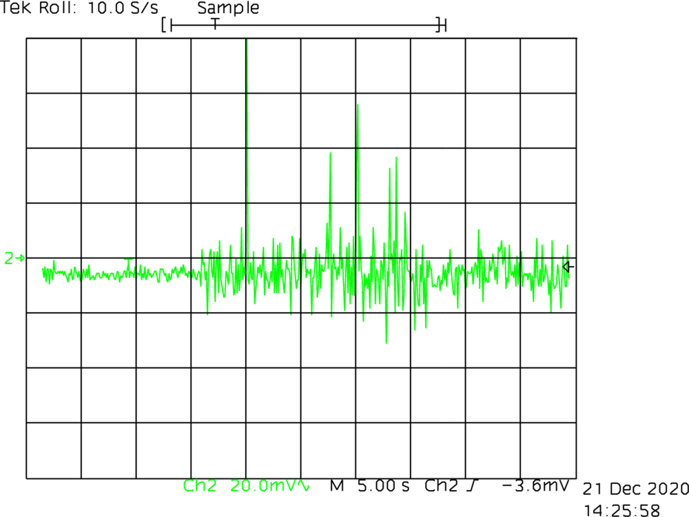
Understanding the Tachometer
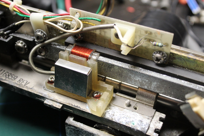
In my box of spare RL02 parts (which came with the PDP-11 for some reason, and not the RL02 drives), I have a crusty old read/write head carriage. This seems like a good thing to experiment on to make sure we understand how the tachometer works. The tachometer is actually just a large coil of very thin copper wire, which moves along a ferromagnetic rail. I placed a magnetic viewing sheet over this rail to see if I could see an alternating arrangement, but I can't, it appears to be a single magnetic with a single polarisation.
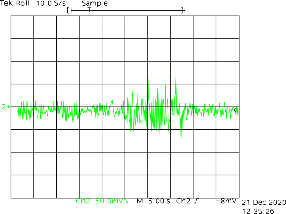
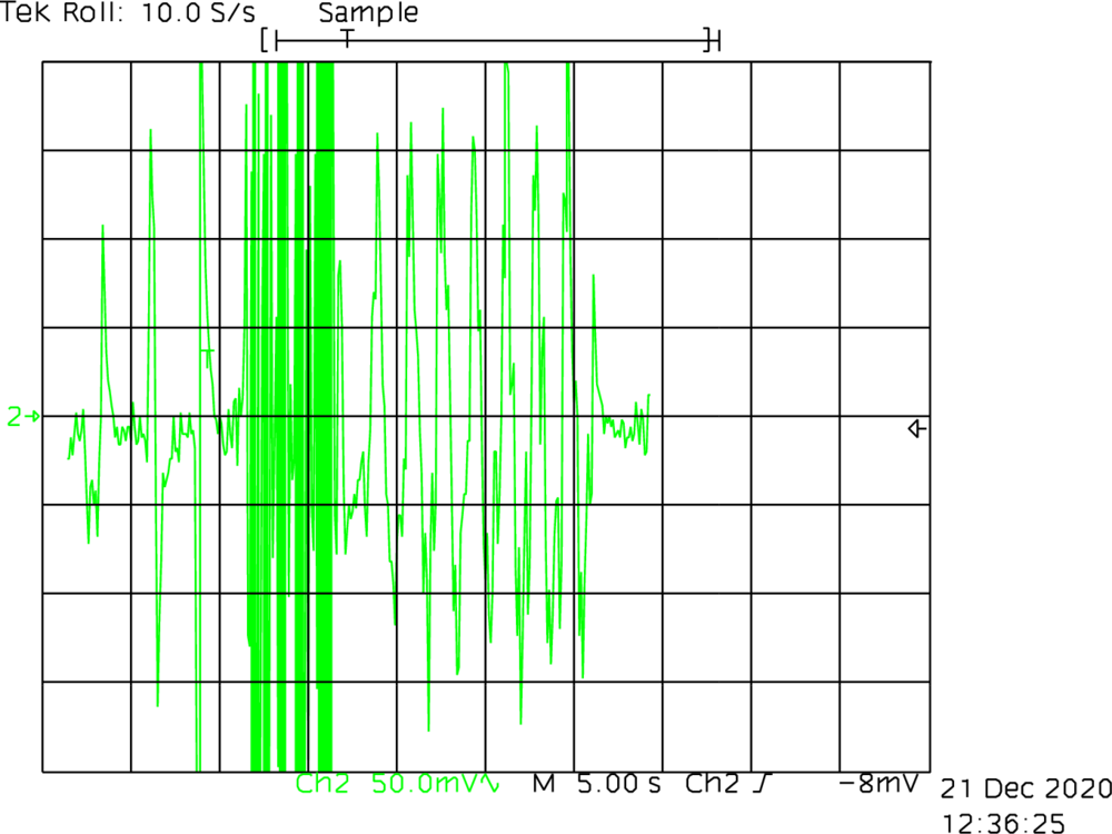
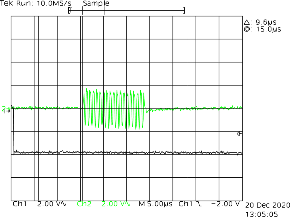
Below I show an oscilloscope dump of the signal from the tachometer without any amplification. First, without movement to establish the noise floor (which appears to be around 50mV pk-pk), followed by a burst of slow back and forth movement, finishing with the carriage in a stationary position again. In the scope dump to the right of this, I show very fast movement produced spikes of around 500mV.
Monitoring Position Test Point As Heads Attempt to Load
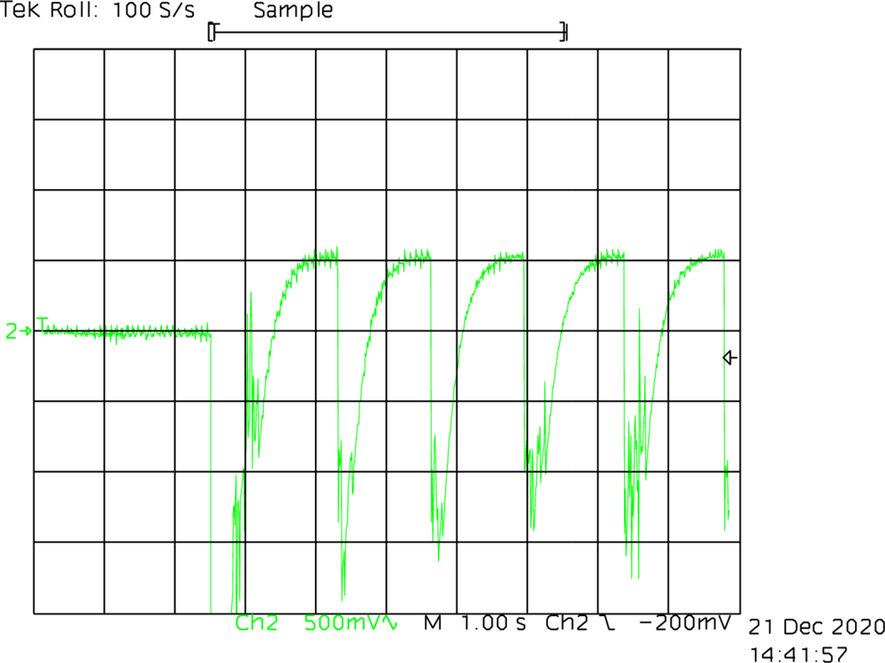
Setting the scope to a low timebase allows us to monitor the position
signal (TP15 on the DLM) as the heads attempt to load. You can see they
attempt this multiple times without success. As the position signal
flattens off, the READY lamp flickers rapidly, before
retreating almost to parked position.
What could cause this? I've monitored the output of the tachometer (both the crusty spare and the installed tachometers), and both have low noise, even while the main drive motor is running. So I think we can rule out that the drive motor would be causing an issue. I did notice that the noise was quite a bit greater with my LED lamp switched on. I've put this scope dump in the notes below. The LED lighting was causing around 50mV of noise when switched on, but I don't think this is anywhere close to enough noise to cause an issue. Attempting to load the heads without the overhead lighting did not fix the problem, unsurprisingly :-).
Given that the signal is able to flatten out before realising a problem indicates that the drive is recognising the servo bursts. This leads me to believe that the tachometer and its related circuitry is most likely fine. The read/write module also seems to be amplifying the signal, but perhaps this is not enough amplitude for the heads to lock onto reliably. This either means my heads are worse than I thought, or all my cartridges are in bad shape. I think either is equally believable.
<2020-12-21 Mon 15:08> I think I will leave this post as is for now. Take some time to think and perhaps try to get hold of another RL02 cartridge. I may also ask on the classiccmp mailing list to see if anyone has any ideas. There are still a few more checks to perform, but none of these can be done unless the heads are able to load reliably.
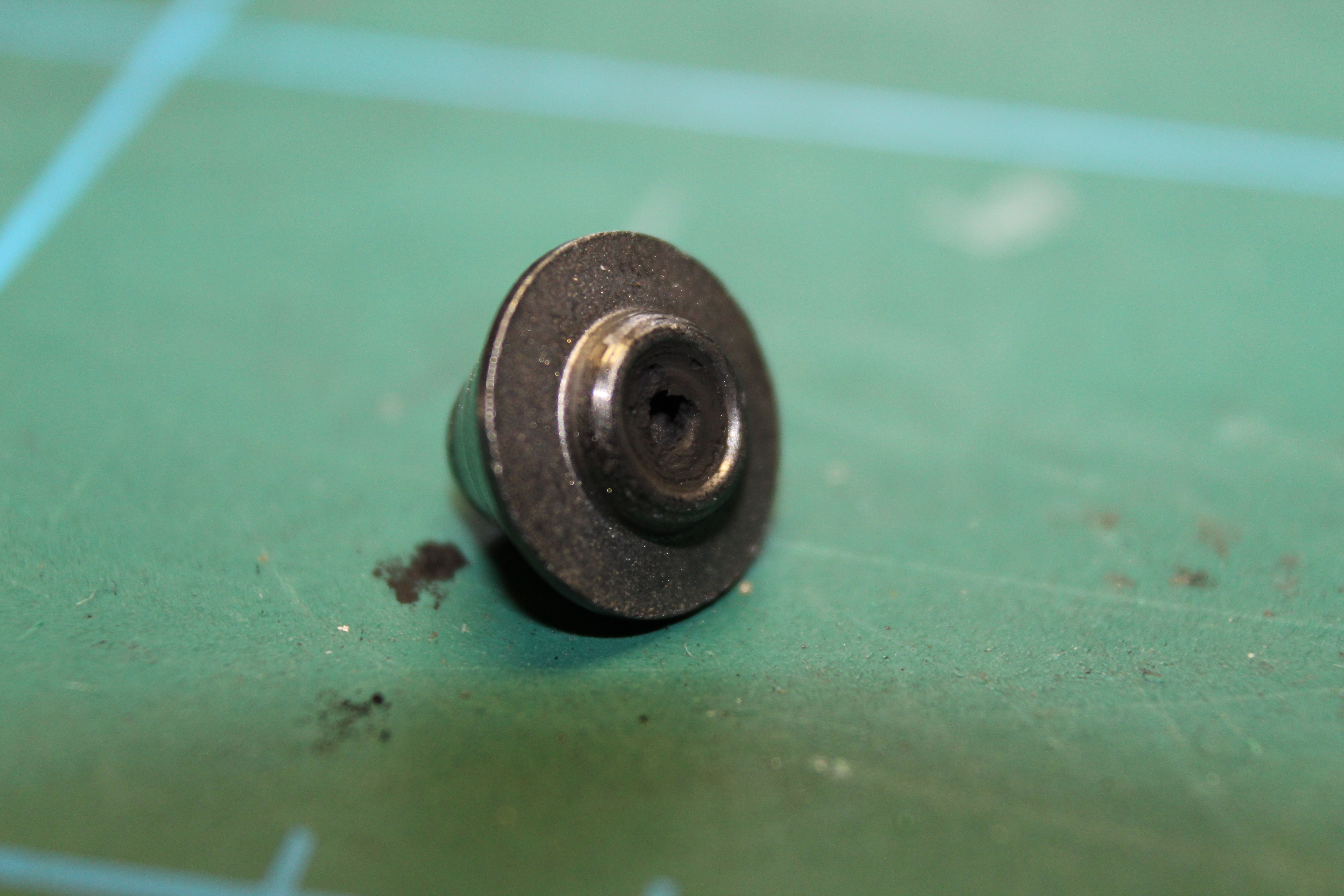
The Grounding Button
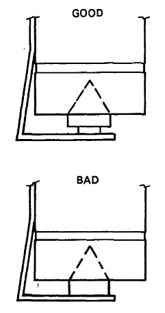
Asking on #classicdec channel and many thanks to
pjustice for making me consider this. The ground button
prevents static build up on the platter, which I imagine happens very
quickly given the speed it spins. To the right I show a good and bad
example of the grounding button, taken from the technical manual. Mine
clearly looks more like the "BAD" example, perhaps even worse. The
graphite has completely worn away. Hopefully this is the source of all
problems?
The problem will be replacing it.
Alright I've ordered some graphite rods. 10mm diameter, and five of them at 10cm each. Hopefully that will give me enough attempts to replace the graphite parts of this brush. I'm currently thinking a drill and some sandpaper…
I've just dome some probing with the multimeter. The resistance to ground from the platter is on average around 400 ohm. Applying pressure to the graphite button, this immediately drops to zero. So there is definitely a problem with this. For a test, I taped some polystyrene (I know…) to the bottom plate, pushing the button in. This keeps the resistance at 0 ohms. Very nice! However, it still does not fix our problem.
The Grounding Button (Part 2)
This part comes from <2022-11-18 Fri 22:35>
I was beginning to wonder whether the lack of a suitable grounding button was causing a buildup of static charge on the platter. One thing I really do not understand is whether or not this would even matter! I started trying to think about it as if it was a balloon.
If you had a statically charged balloon and rotated it in a fixed position, next to a microphone coil, would that produce a signal on the microphone? I would think not! The field is stationary because it's even across the entire surface of the balloon.
What if the balloon had tiny magnets on it? Would the tiny magnet's cause the static field to be uneven across the surface of the balloon? I start to think it might… and so, both the uneven static charge, and the magnets, would both have an affect on the microphone coil. Well… This magnet covered, statically charged balloon, doesn't seem too different from an RL02 platter. At least, that's what I convinced myself of.
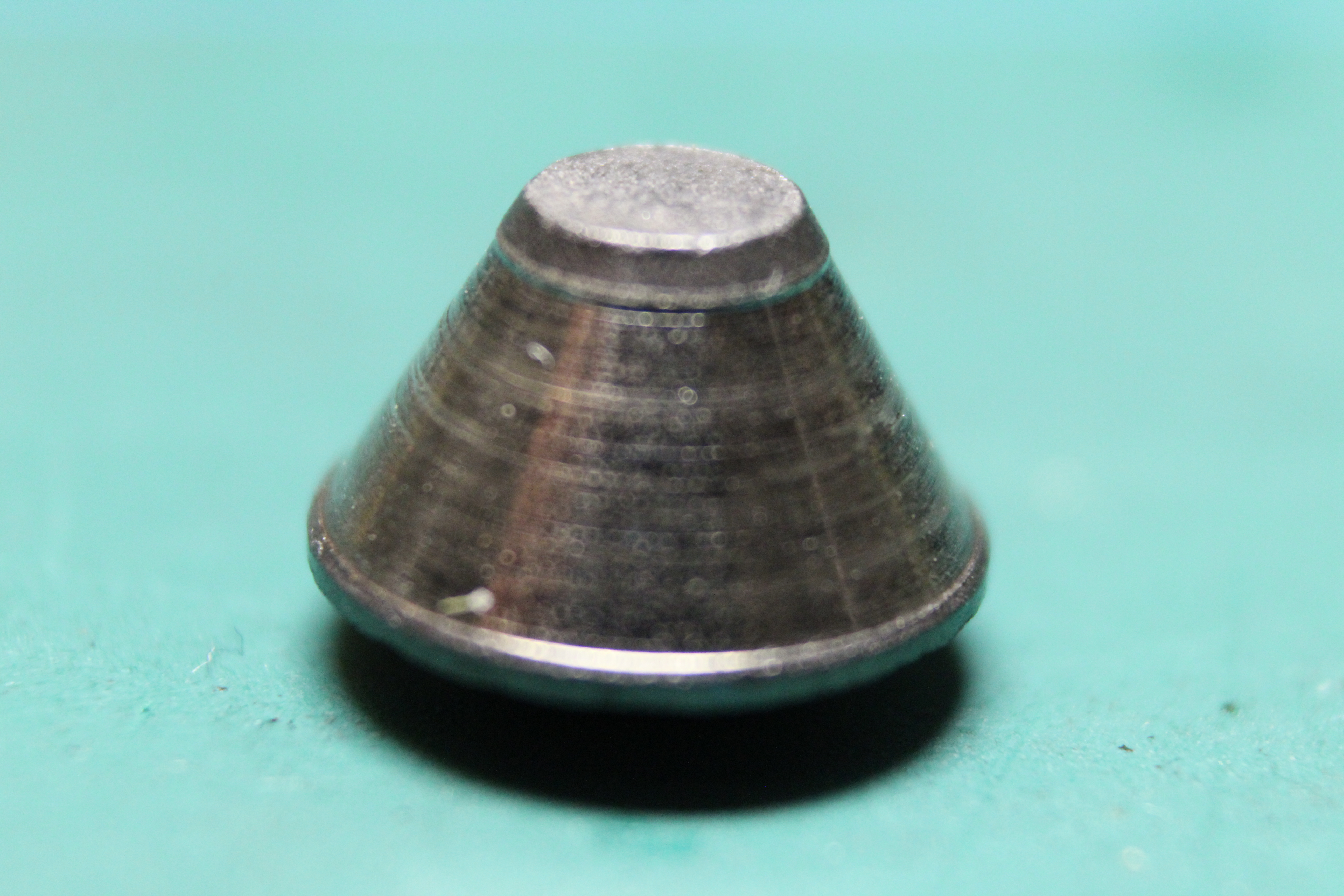
Regardless of whether this is accurate or not (I really have no idea!), the grounding button exists within an RL02 drive for some reason. In the worn state, it was not having the intended effect, so I made a new one.
I purchased some 10mm carbon rods off eBay, but then they arrived from Amazon Prime, so I left negative feedback. Surely people can't make much money from a few pence on each order? Using the mini lathe at Nottingham Hackspace, I was able to turn these down to the correct shape.


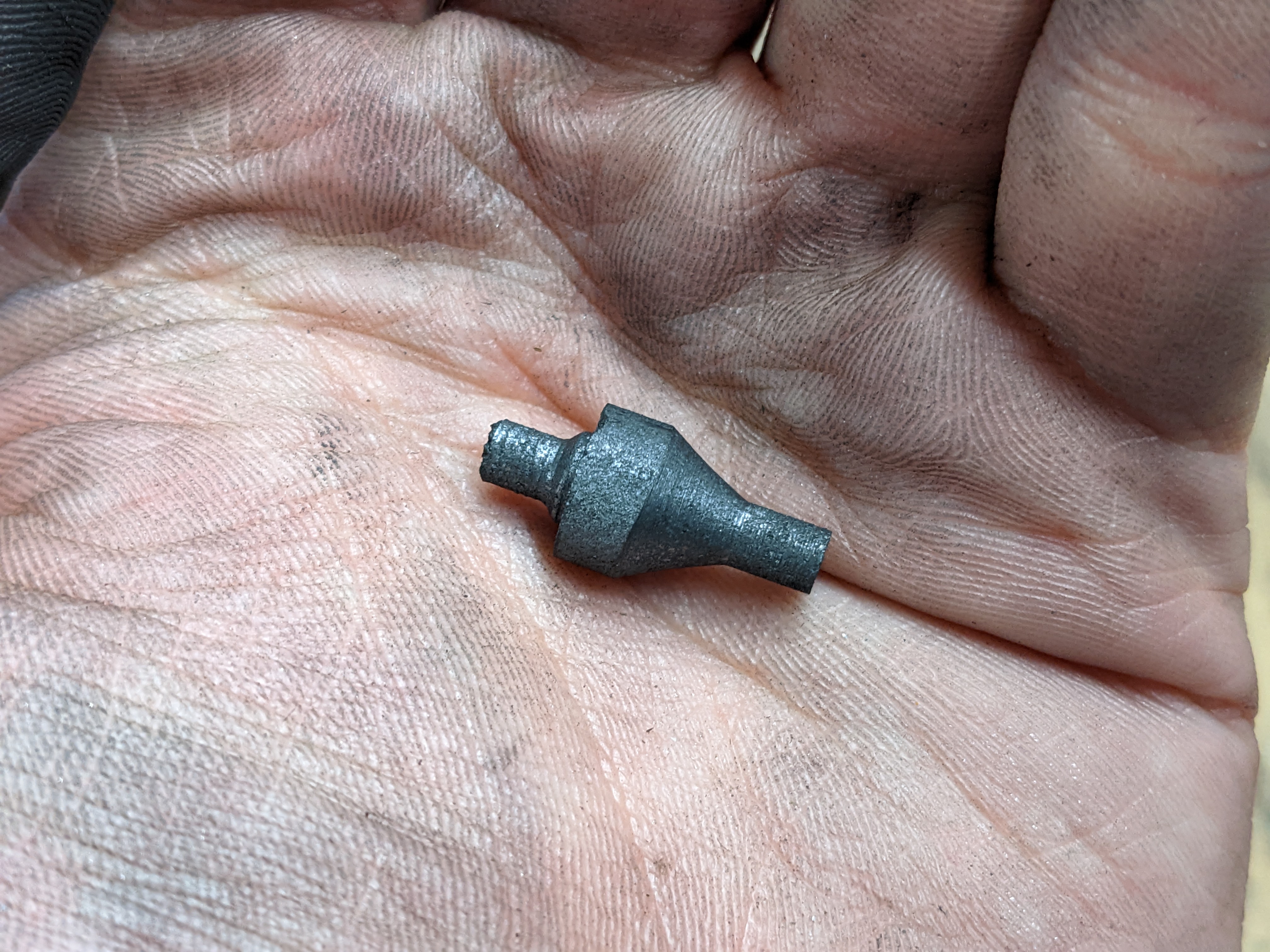
It was a bit messy, and took me several attempts to make one. While it turns really nicely, it is very brittle and will break off very easily if chunks are taken out too quickly. In the first photo, you may also notice that there is a vacuum cleaner nozzle. I decided that since the "chips" would be so small, running a vacuum cleaner should help suck up most of the stuff. Quite a bit still fell onto the carriage but it was easy enough to clean up.
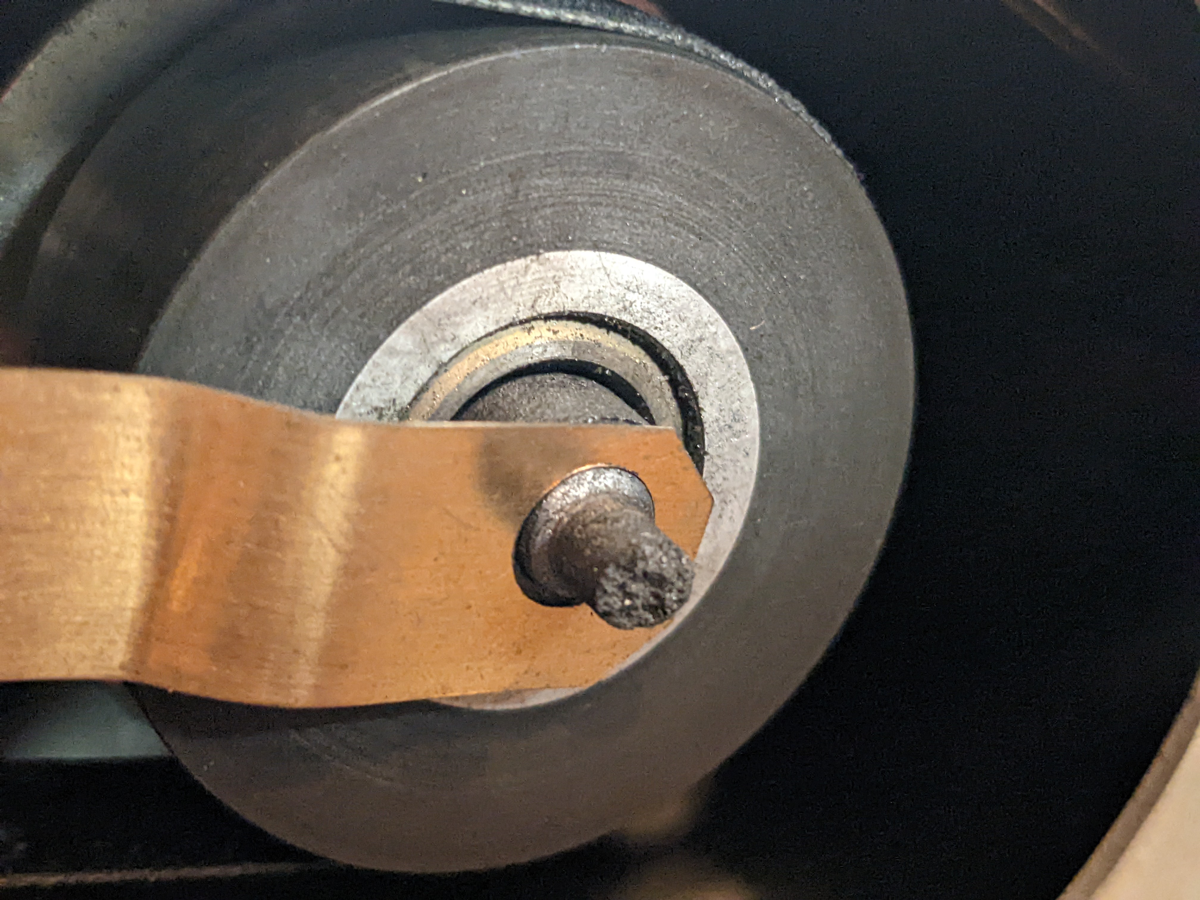
To cut a long story short, I installed these and did some testing. Unfortunately I did not find an improvement but I haven't yet checked the signals on an oscilloscope - my tests was more of an all or nothing "did it fix my problem?" The resistance between the spindle and chassis dropped to 2.5 ohms, from 400 ohms, so it definitely improved in that respect.
Investigating the 'Tachometer AC Noise Pickup' problem
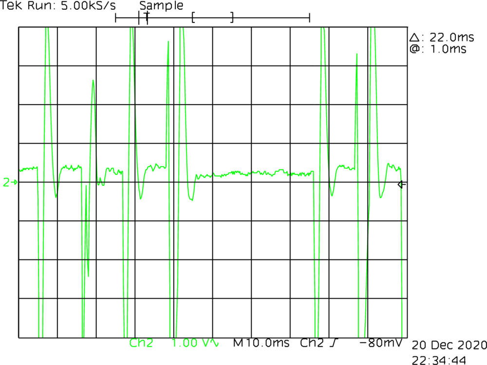
I was chatting to a friend, Adrian (thank you for helping me investigate!), about this post and he mentioned the output from the summing amplifier (See Tachometer AC Noise Pickup Check) doesn't look like noise that might be caused by the drive motor. He instead suggested that it looks like an op-amp (or something) is clamping the voltage. Referring to the schematics, the summing amplifier output is clamped by two 5.1V zenner diodes. The oscilloscope screen cap is cut a little short, but it looks like 5.1V might be the peak voltage of these.
NON INVERT L with amplified tachometer signal
(green).There are a few places this spike could be introduced. The amplified
tachometer output is combined with the output of a MOSFET and fed into
the summing amplifier. The base of this MOSFET is controlled by a
NON
INVERT L signal. The source for this mosfet comes from the
VEL
COMMAND
and another MOSFET whose base is attached to
POS MODE
L
.
Tracing this signal back, it appears to be present on the base of the
first MOSFET, i.e. the NON INVERT L line (shown in the
scope dump to the right). This NON INVERT L signal comes
from the DIRECTION signal after going through an AND gate.
Tracing back a bit further, the DIRECTION signal comes from
the SEEK CONTROL ROM, which I didn't even discuss earlier
while describing the count ROM.
Alright, let's dig a bit further. What is this so called seek control
ROM? To be honest, I've run out of energy to even try and understand
what is going on here. However, rather conveniently, the technical
manual has a nice table describing the outputs for a given set of
inputs. I have included the table to the right, highlighting rows which
result in the DIRECTION signal being high.
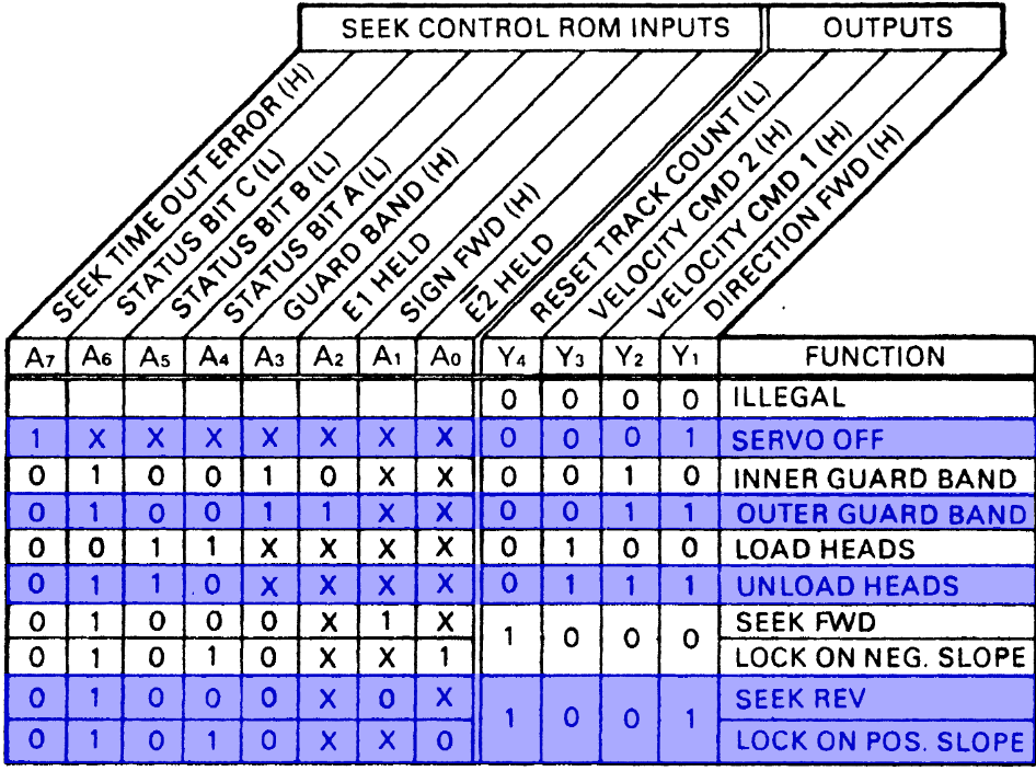
This is certainly very helpful. Presumably this pulse is within "normal" range, but it does seem quite aggressive. I feel comfortable ignoring the first potential cause for this, since it happens when the jumper to ignore the seek time out error is installed. The second function listed is to move off the outer guard band, which to be fair, they are likely hovering over. I'm not completely sure what it means by "Unload Heads" - does it mean it needs to unload the heads, or the heads are unloaded? The final two reasons are for "Seek Rev"(ersal?) and "Lock on Position Slope". Hmm. I guess I need to probe all four of these output lines to figure out precisely which event is being triggered. I will do this tomorrow. Hopefully this will help us establish the reason for the erratic head movement.
<2020-12-22 Tue 01:01> I was about to go to sleep when I
thought "why on earth is that signal being pulled negative?", and you
have to admit, it's a good question… But also, why doesn't it stick to a
binary output? The first output of this ROM is the
DIRECTION signal. It is tied to a +5V rail through a 4.7K
resistor. So presumably the ROM leaves 'HIGH' states floating and
grounds 'LOW' states? Besides, this DIRECTION signal
travels directly from the ROM to the DC Servo module via a ribbon cable,
and goes directly into a NAND gate. I don't understand what could
possibly be pulling this voltage to -5V.
<2020-12-22 Tue 13:40> I checked this signal again and it does appear to be either 0V or 5V, as I would expect. I shouldn't be checking things when tired….
Most Likely a Pair of Bad Cartridges?
I've been carefully monitoring the READY lamp and servo
bursts while the heads are loading, and have come to a new theory as to
what the problem might be. The READY lamp flashes not when
I see the S1 burst, but when the heads are just before the outer guard
track. This seems very stupid, but I think I understand why.
During the "Read Signal Amplitude Adjustment" step, I probably set this too high, compensating for bad cartridges. Setting the amplitude too high also amplifies the noise floor, to the point that the drive may believe it has found the first track, but is unable to detect the servo bursts, thus causing the heads to oscillate back and forth trying get aligned properly.
So, I'm hoping I can get hold of a known to work cartridge. Wouldn't that be nice!
BC80J-20 Cable vs a Ribbon Cable
This part comes from <2022-11-26 Sat>
Last year I ordered an RL02 terminator with a cable (BC80J) for an RL8A. For some reason, I assumed this cable was only for PDP-8 and wouldn't work with my PDP-11 and its RLV12 controller. This week I was shocked to find that it has the same number of pins, so I gave it a try. Unfortunately, the fault light came on immediately. I decided to look up the engineering diagrams to see if that made sense and whether I could build an adapter to go from BC80J to BC80M, but it turns out the pinouts were the same. The only difference is that the BC80J doesn't have an outer mesh sleeve, but that should still be fine, so came to the conclusion that there must be an issue with the cable. After a bit of poking and prodding, I found that a couple of wires were not correctly terminated in the bulkhead connector. After a quick smushing the cable (with terminator) seemed to work and gave the same results as using a straight through ribbon cable without a terminator.
The State ROM
This part comes from <2022-11-27 Sun>
Within the RL02 drive, state is primarily dictated by the State ROM. This is accomplished by using several signals as addresses to a given state, stored in the ROM. These signals come from other parts of the drive, such as determining whether the disk is at the correct speed, whether the heads are sitting over track 0, and whether an error has previously been detected. The output of the ROM is four bits - three of which are fed into a binary coded decimal (BCD) decoder, this being a standard TTL SN7442 chip, which provides ten logical states which the drive can be in. These drive states include things like whether the drive should position or velocity mode (described in the Position Signal Gain Check section), whether the drive should spin down, or lock on to a track.
Given my confusion which why this drive wasn't working, I was wondering if the drive is actually doing what it thinks it is doing. So, I booted up the logic analyser, which unfortunately didn't turn on. Well, it sort of did, but the display wouldn't show anything, so that's another thing to fix, another time. I ended up caving and purchased two of the cheap USB logic analysers off eBay. I've actually been really impressed with these - they work amazingly under Linux using PulseView and the experience is so much nicer than what I could ever have gotten from my HP logic analyser.
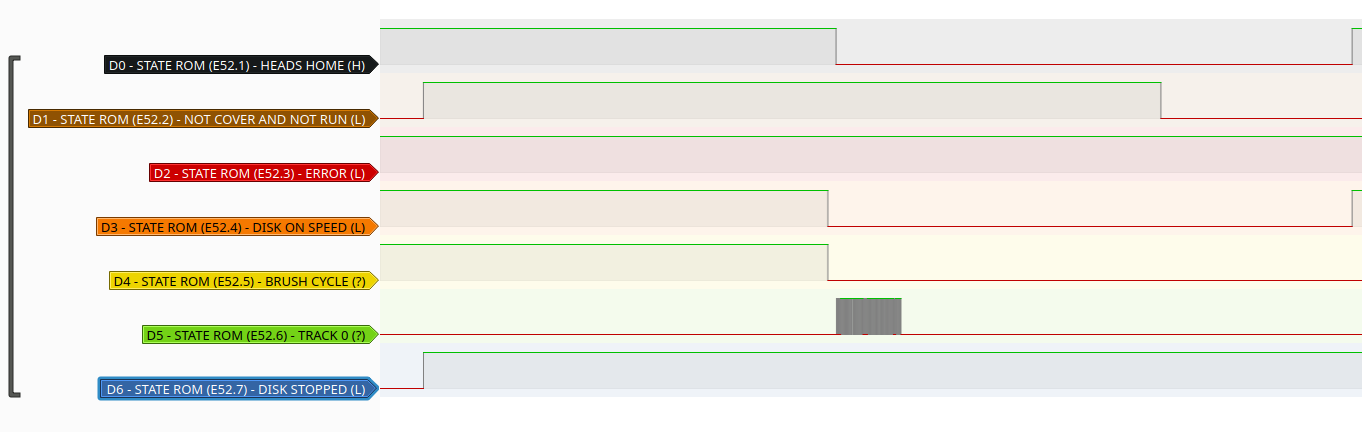
The logic trace above shows the seven inputs into the state ROM
address pins for approximately 23 seconds. Within the first couple of
seconds, you can see where I press the LOAD button and the
drive starts to spin-up. The "DISK STOPPED" signal, which is active low,
goes low. It takes about eleven seconds for the disk to reach it's
target speed, at which point the "DISK ON SPEED" signal, which is also
active low, goes low. Almost immediately after, the TRACK 0 moves from
low state and flutters between high and low for a couple of seconds
before giving up. Given that the drive was reacting correctly based on
what these signals do, I feel fairly confident in declaring this part of
the circuit as "working". It was still a fun foray into USB logic
analysers, PulseView and the State ROM, though.
Lock On
This part comes from <2022-12-01 Thu>
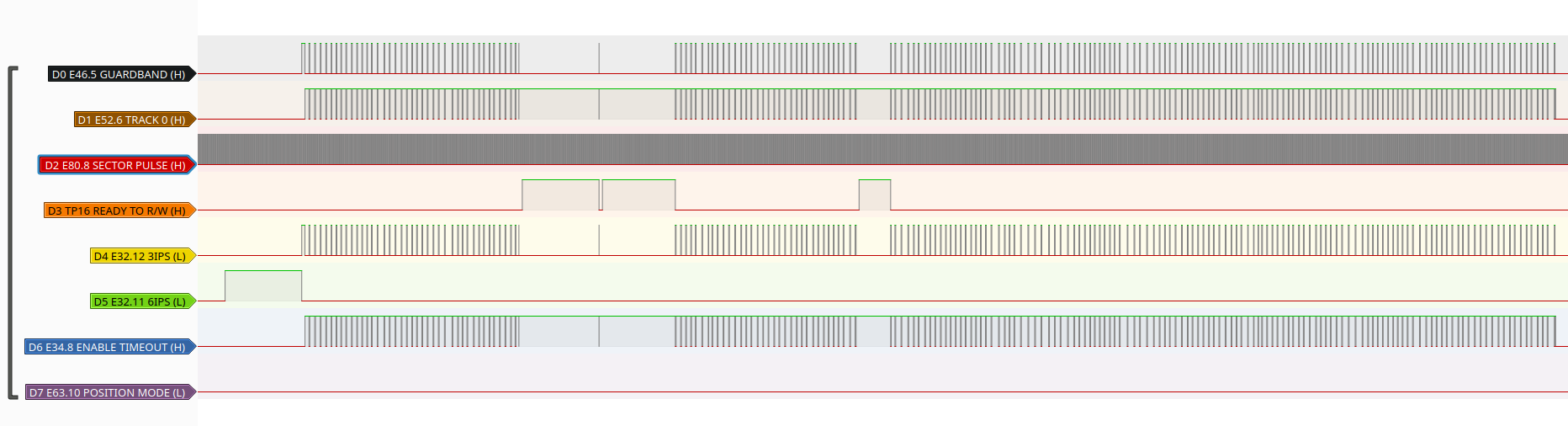
The fluttering of track 0, mentioned from the previous update, made me want to further investigate this issue with locking onto a track. According to the theory of operation manual, the drive needs to be in a steady locked-on state for a couple of seconds before it will enter the "READY TO R/W" state. Until this happens, the drive will not accept commands to seek, read or write. I set out to monitor eight more signals within the drive, based on what I think would be helpful, given my understanding of the drive.
- E46, pin 5 - Guardband (active high) - This will allow us to see when the head is over the guardband. The drive knows this because only servo 1 bursts are visible.
- E52, pin 6 - Track 0 (active high) - This allows us to know when the drive is over track 0. The drive knows when this is the case because by detecting a transition from only servo 1 bursts to seeing servo 1 and 2 bursts.
- E80, pin 8 - Sector Pulse (active high) - We'll be able to see that the drive is accelerating correctly by the intervals between these pulses.
- TP16 - Ready to Read/Write (active high) - Once the drive is over track 0, the drive begins a timer. If it remains on the track for 1.5 seconds, the drive raises the ready to read/write signal. This allows us to see if the drive thinks it is ready.
- E32, pin 12 - 3 inches per second (active low) - This signal instructs the carriage to move forwards at 3ips, which should happen while searching/seeking for tracks, but not during the head load.
- E32, pin 11 - 6 inches per second (active low) - The drive loads the heads at 6ips, so when this signal goes low, the heads will be moving onto the platter until the guardband is detected.
- E34, pin 8 - Enable Timeout (active high) - The timeout starts once the drive is over track 0 - I mentioned this earlier for the ready to read/write signal.
- E63, pin 10 - Position Mode (active low) - Once the drive has locked onto a track, the drive moves into position mode.
Since these lines are spread out over quite a large area, the wiring became quite messy! The trace below shows these states changing over the course of about 14 seconds. We can see the heads loading correctly at 6 inches per second. As soon as the guard band is detected, it switches to 3 inches per second, moving forward to find track 0. Eventually it finds it, but only for 1.1 seconds, before losing it briefly. So close to entering position mode!
Having thought about this for a while, I think all of this is normal, and it actually is struggling to lock on, possibly due to a mechanical fault. If the spindle bearings are worn, the tracks will be moving a lot more than they should. So, that's what I'm going to do next - take apart the spindle assembly and inspect / replace the bearings. Scary!
Lock On (Follow Up)
This part comes from <2022-12-03 Sat>
I was thinking about my RL02 drives today and whether there are any arguments for or against my "theory" that there's spindle run-out. Considering that an RL02 drive has 512 tracks, and those tracks need to exist in only 50mm-ish of platter, each track must only be about 0.1mm. I'm not sure I would be able to notice 0.1mm of wobble in a spindle but I can review the logic trace from yesterday to see if there are any patterns.
Fortunately, PulseView allows you to add calculated traces, such as decoding SPI or GPIB, but it also lets you do things like count transitions, such as rising or falling edges. Better yet, it allows that count to be reset using a state transition of another line. I decided I'd like to count the number of sector pulses between losing track of track 0.
It turns out, the heads lose track every 20 sectors or so. An RL02 cartridge has 40 sectors per track. The heads are like a planet in orbit around a track - except in this case, the heads are stationary and the orbit is rotating. Ideally, this orbit would be circular, but due to spindle run-out, it is an elliptical orbit. An elliptical orbit has a periapsis and apoapsis. The perapsis is the short side of the orbit, where as the apoapsis is the longer part of orbit, around the centre of mass (the spindle, in this case). When the heads are at the periapsis, the heads will be closer to track 1 than track 0, and when the heads are at the apoapsis, the heads will be closer to the guardband than track 0. This might explain why the heads lose track twice per orbit (alright, rotation) instead of just once.
The one thing stopping this from making perfect sense is that in my logic trace, the guardband state goes active every time it loses track 0. Still, I think taking the spindle apart and replacing the bearings could prove useful.
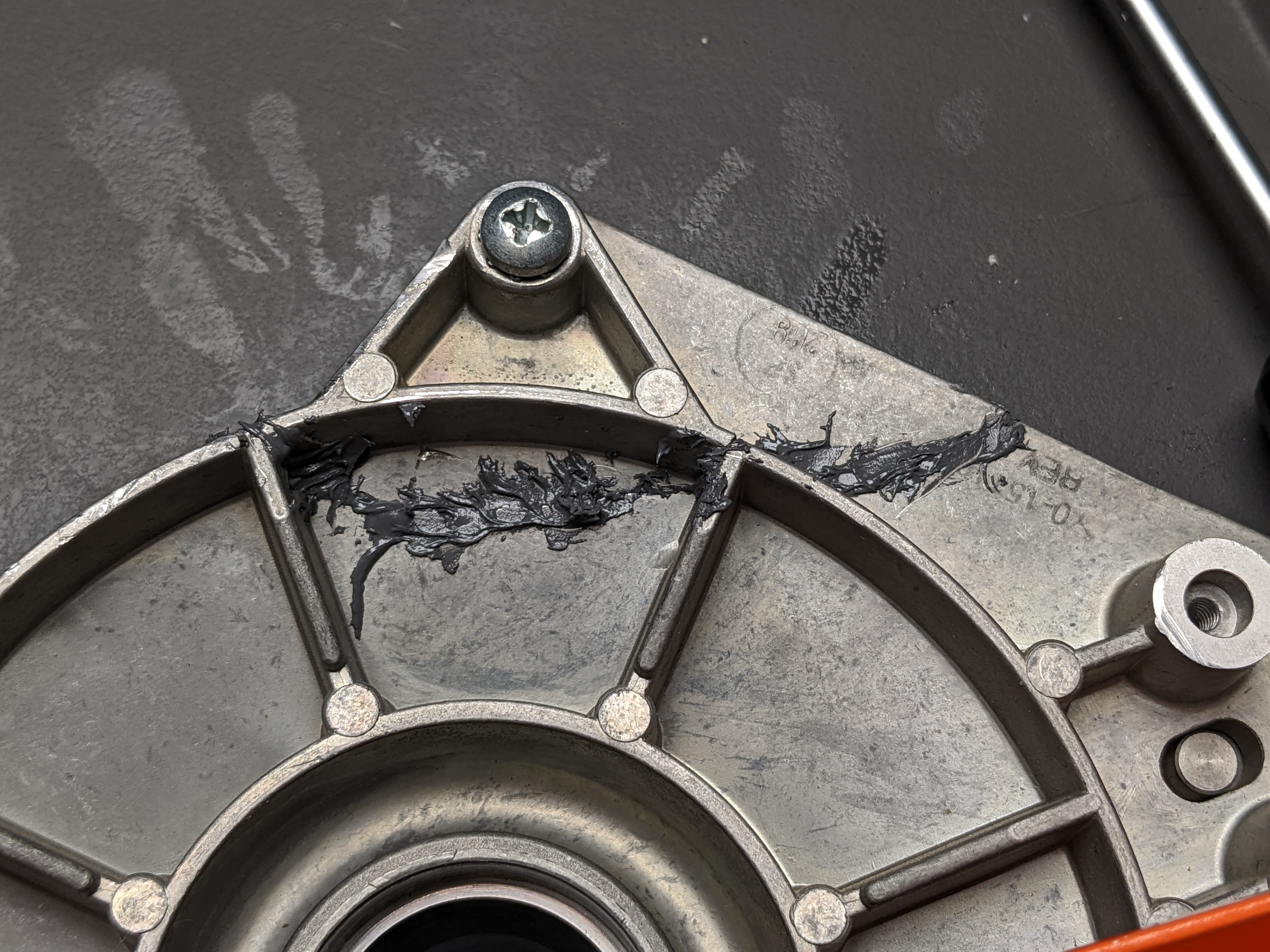
Removing the bearings
This part comes from <2022-12-04 Sun>
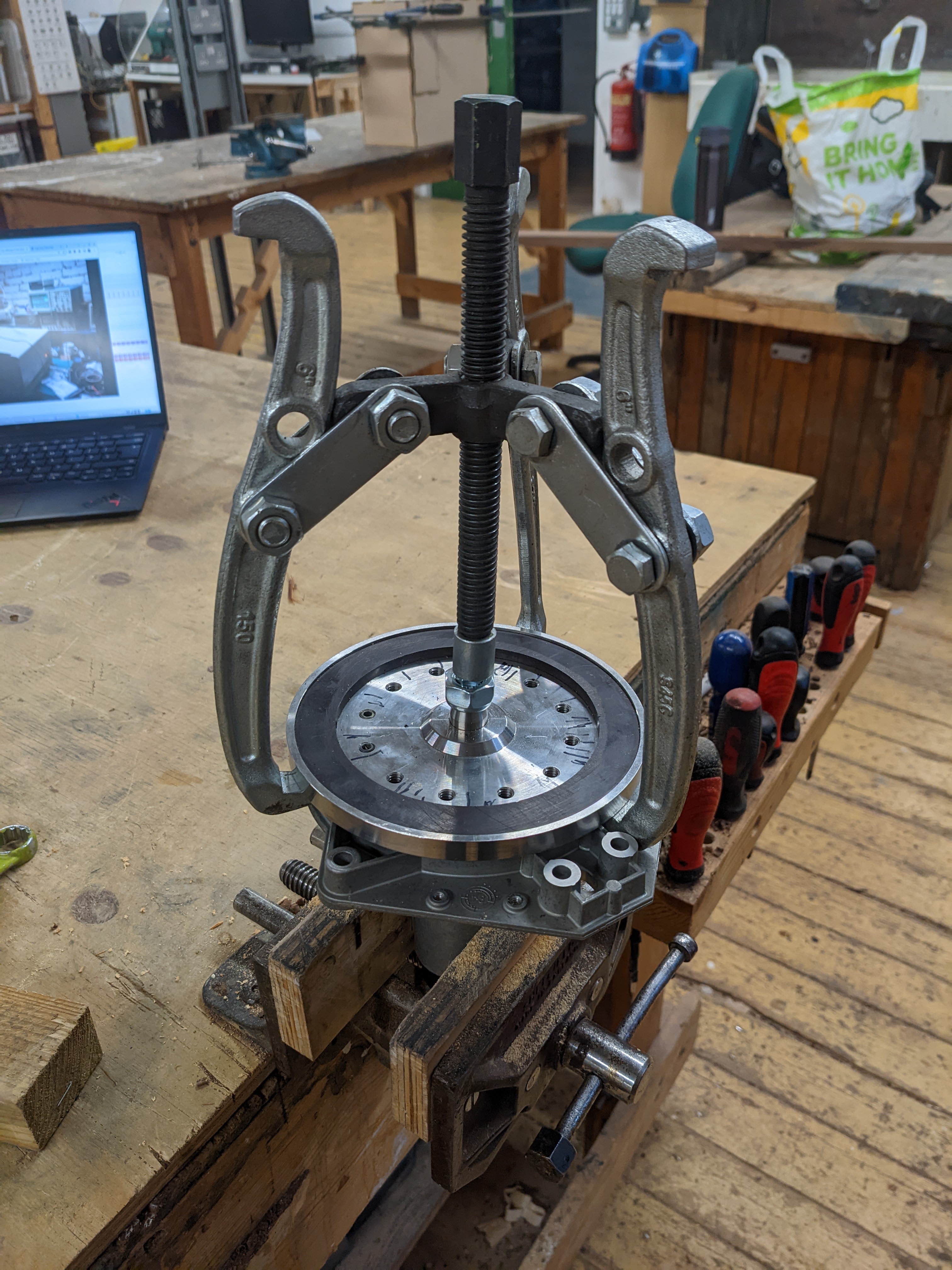
I took the spindle assembly into the hackspace today to try and remove the bearings for measuring. I used a claw/grabby/thingy for pulling off the top spindle plate and then removed the shaft with a mallet.
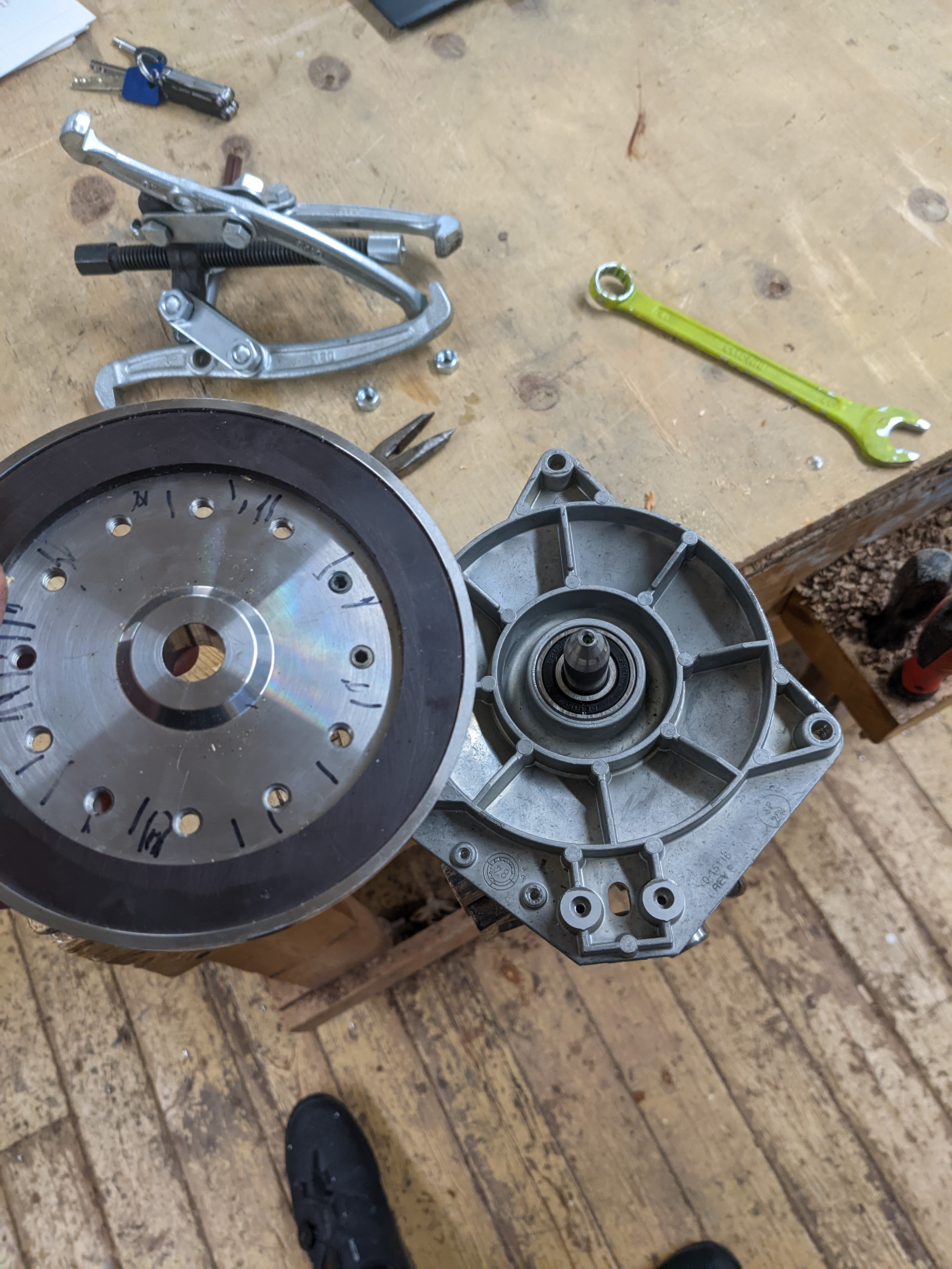
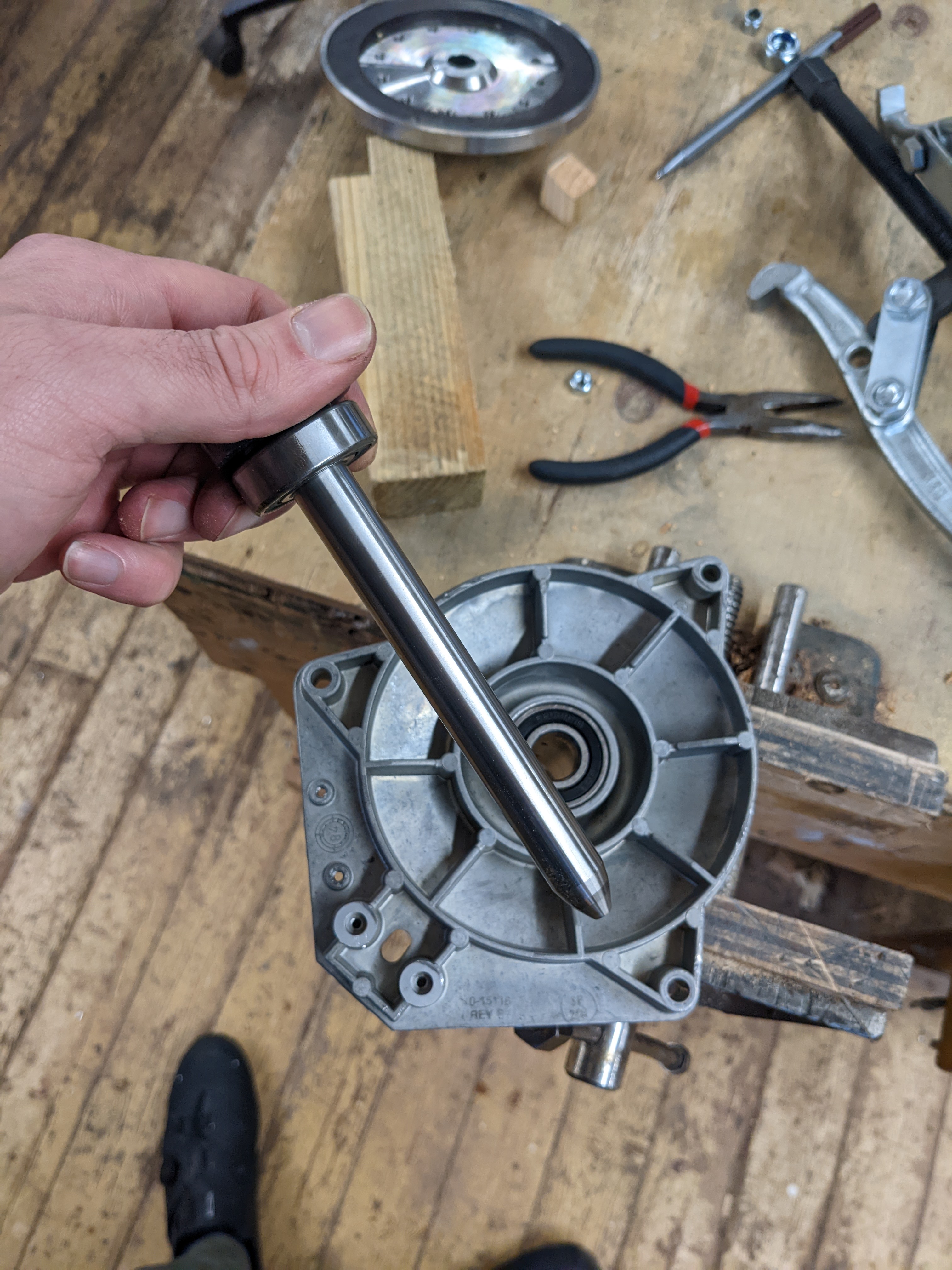
This came out quite easily but I still had a bearing stuck in the assembly. I first tried using a washer to push the bearing out, with the bearing puller being used as a bearing pusher (does that make sense?). Unfortunately this did not work well and I snapped part of the assembly. Using a steel shaft and a mallet worked better. I've put the spindle assembly back in the drive and added JB Weld along the seam of the crack. Hopefully this will be sturdy enough. My understanding is that any small side to side misalignment does not matter and can be adjusted for - so hopefully this will be ok.
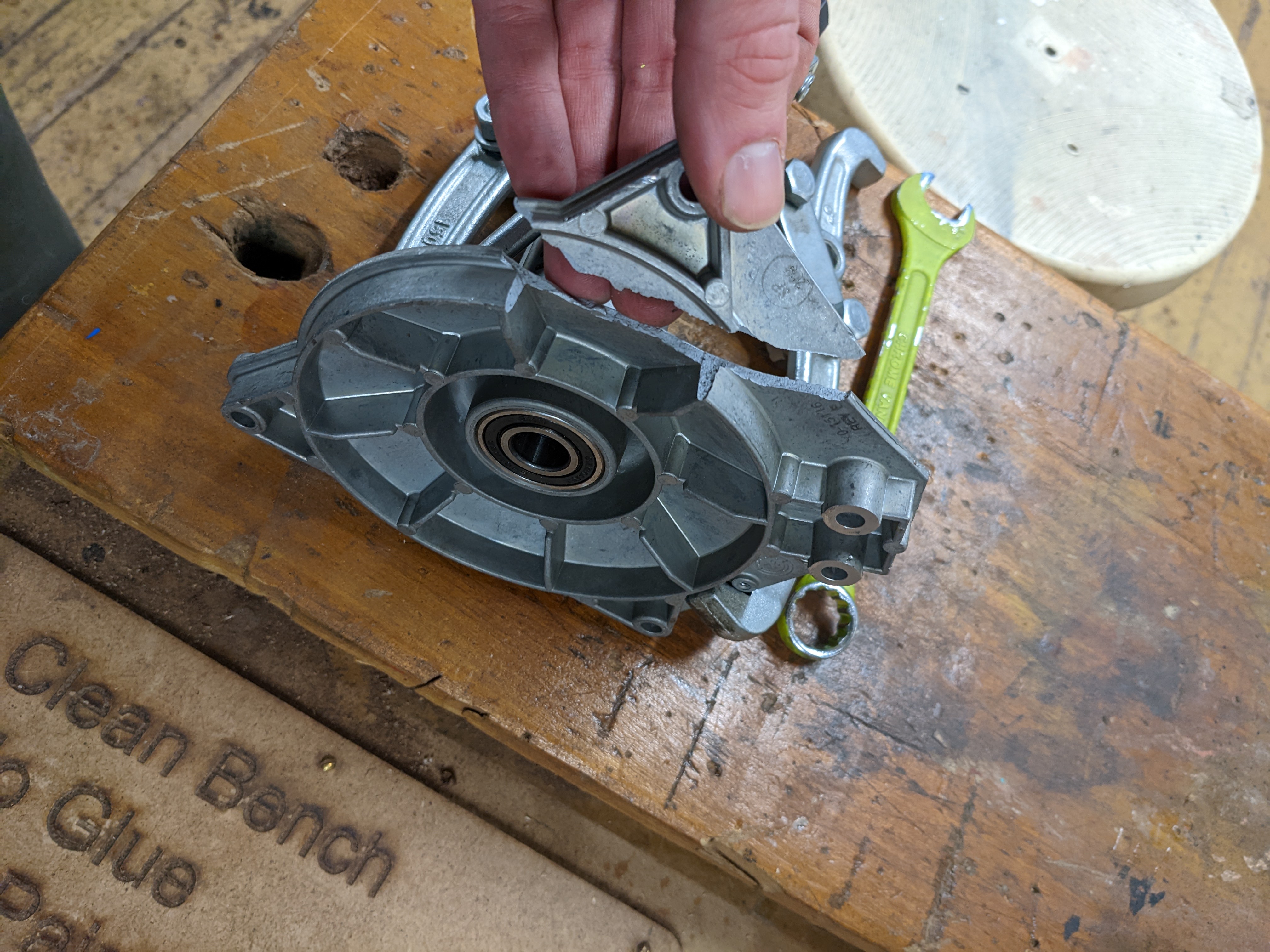
I still have another bearing and the pulley mounted on the shaft. My attempts to remove this today were unsuccessful so I will apply some penetrating oil and give it another go some time this week. Wish me luck! In the meantime, I've placed an order for new bearings. These have an inner diameter of 15mm, an outer diameter of 35mm and a race width of 11mm. Hopefully they are precise enough to fix my issue!
Checks, Adjustments and Alignments - Continued
I hope eventually I can do the following checks, and will update this post if that ever happens.
Velocity Profile Check
The purpose of this check is poorly described in the technical manual. However, I believe the point is to verify that the heads move quickly enough. They should be able to move between a single track in a time between 80 and 96mS. If they can't, there may be an issue with the DC servo module, or something might be wrong with the carriage.
Performing this check would require that the PDP-11 be able to communicate with the RL02 drive correctly. This doesn't seem to be the case last time I checked, so I'll leave it until I've made some more progress elsewhere.
Servo Drive Motor Current Check
This test measures the current used to drive the read/write head carriage motor. It also requires us to type in a program which oscillates between track 0 and 511. Leaving this for now.
Access Time Check
The purpose of this test is to verify that the performance is ok. We currently know this not to be the case, and it also requires the oscillating seek program. I will be leaving this one for now too.
Notes
This section contains things I either referred to within the rest of the post, or I just thought were mildly interesting and worth putting down here.
Formatting RL02 Cartridges
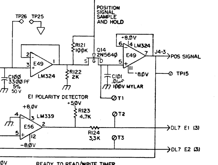
Back in March 2018, I was looking through the RL02 Schematics and spotted a note on page 58 of the Revision B (Nov 1979) engineering drawings. The note reads,
- T1-T3 ARE PADS FOR FORMATTER WIRING (NO ASSEMBLED PARTS).
This strongly suggests that the servo burst data is written using modified RL02 drives during the manufacturing process. The schematic (right) is part of the Drive Logic Module, and my brief guess from looking at it, would enable writing of the servo burst data. I emailed Mark NF6X about this and he believes such a modified RL02 drive might include an absolution position sensor to the read/write head actuator (or just replace that whole assembly with something else. Neither of us are sure what other modifications would be required to the drive, but I hope someone smarter than me can investigate this one day. Ah, by the way, I emailed Mark about this because he had previously posted a thread of VCFed about low level formatting of RL02 cartridges, and how it might not be "too difficult" to modify a standard RL02 drive. I hope this is the case! My main concern about this is that I believe the servo guard bands are written with a much stronger field. I'm not sure if standard heads could handle such write current.
Performing alignments is stressful
While moving the heads back and forth, my watch decided to alert me that I am stressed and need to do some breathing exercises. Of course, I told it to be quiet. However, I will agree with my watch. It is stressful! I am very terrified of damaging a cartridge or my RL02 heads. This is likely not helped at all by how shaky my hands get sometimes.
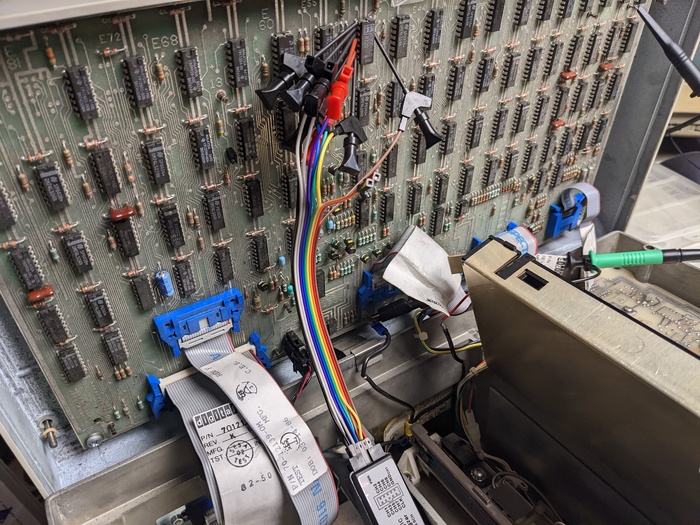
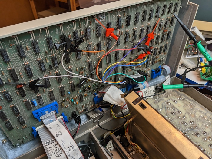
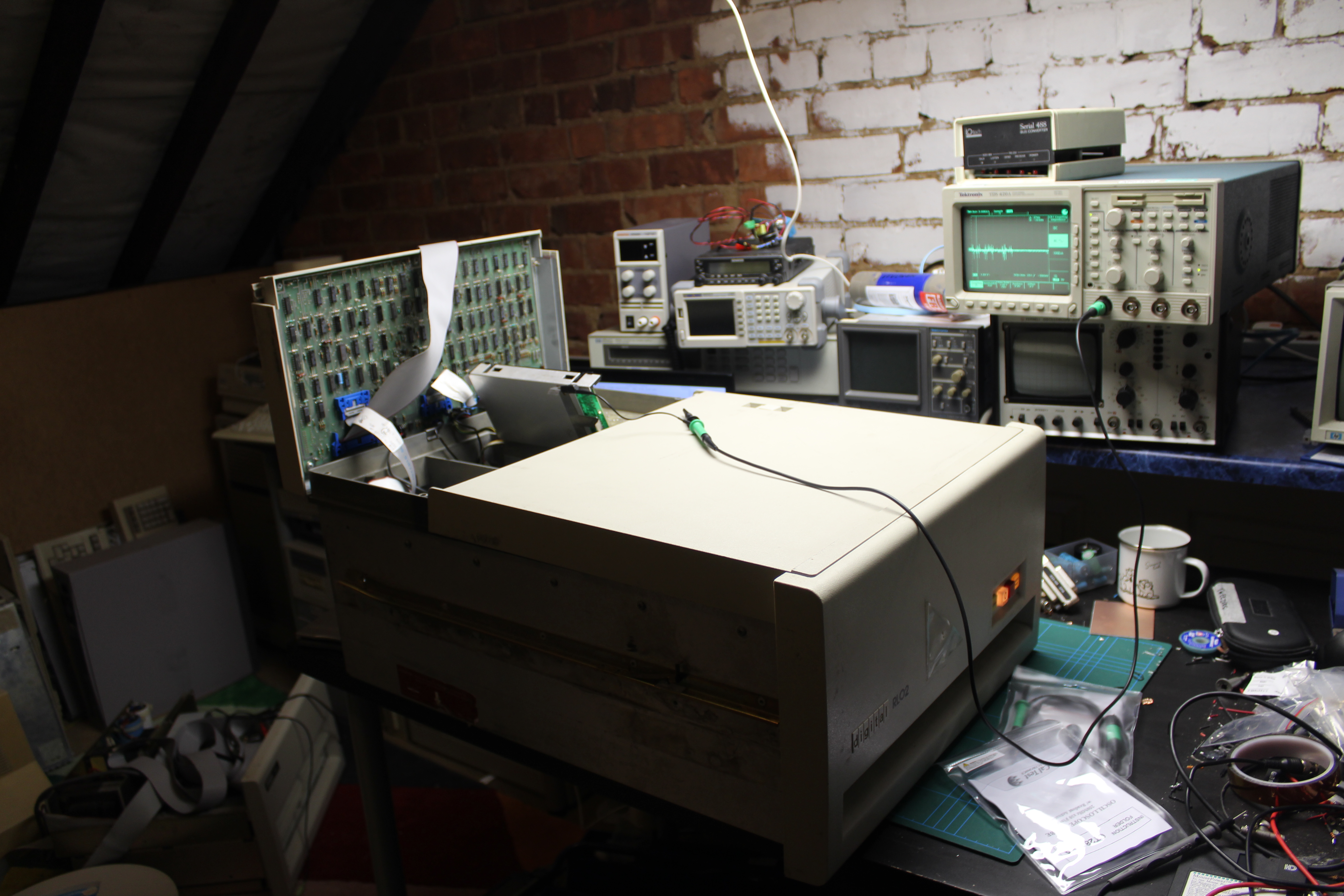
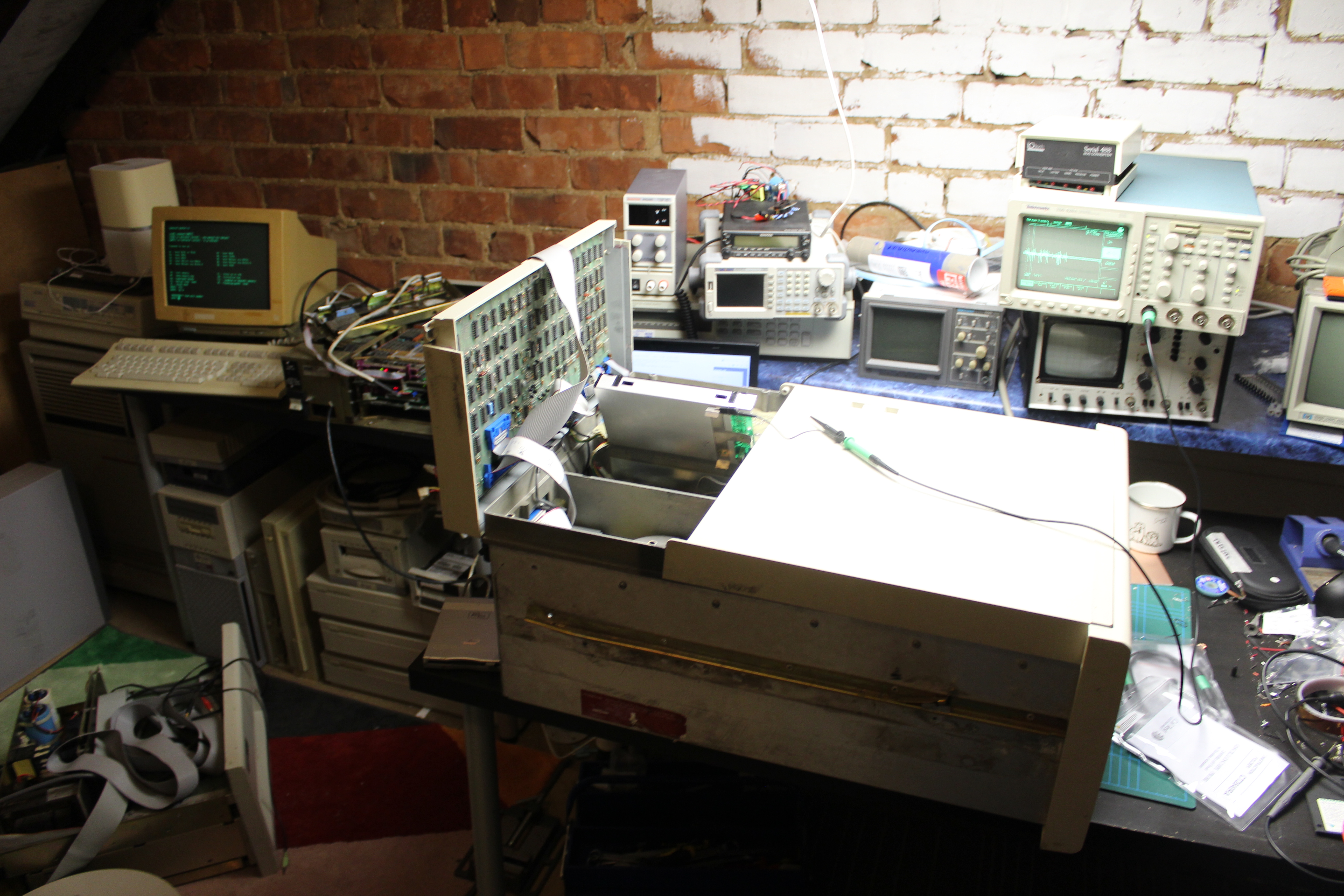
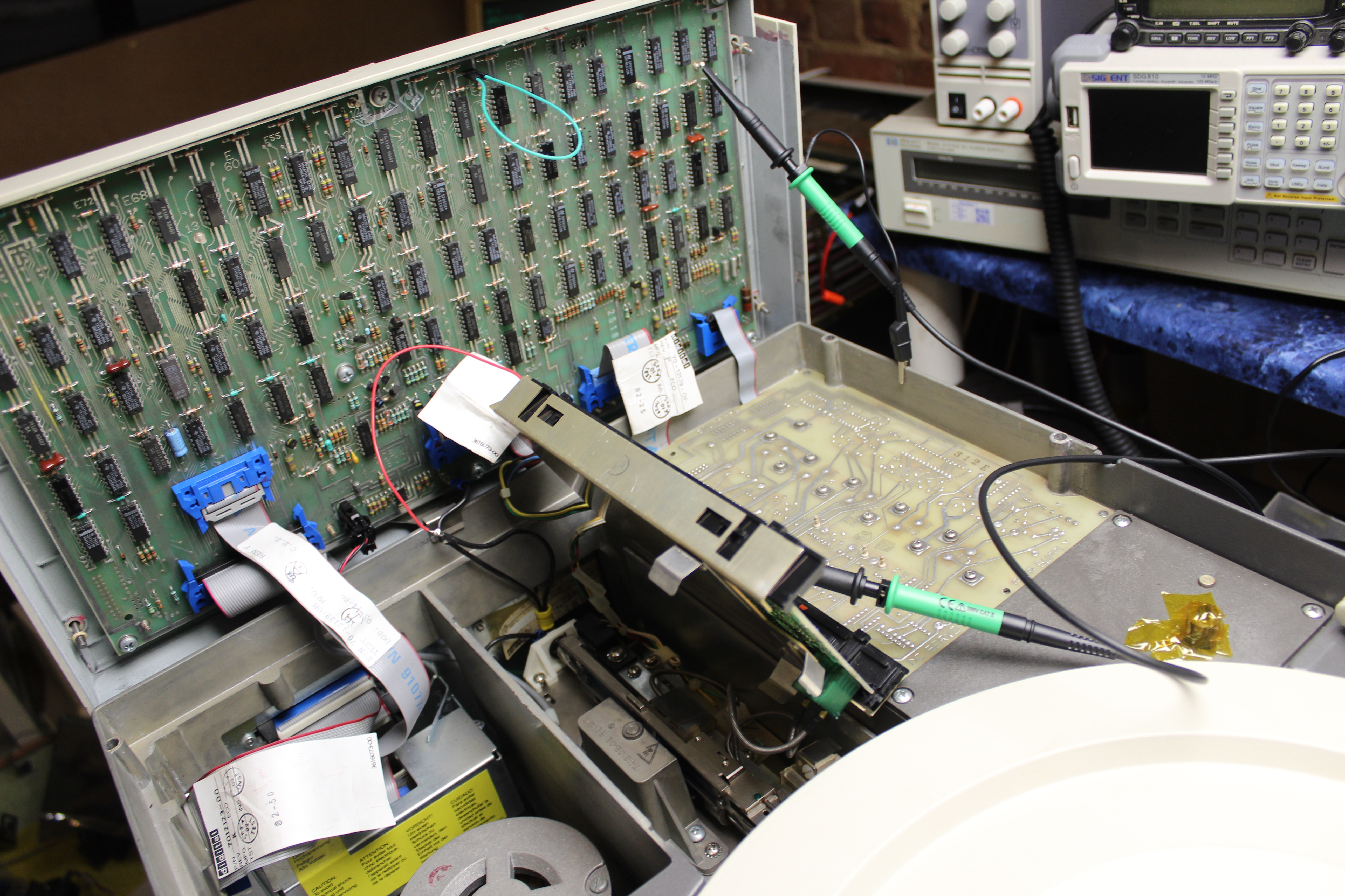
Some photos from 19th December 2020
These photos are not of much use, but I will put them here anyway. The current set up is a bit nicer than my last attempt at repairing these drivers. The scope is nearby and I have somewhere to sit. The PDP-11 is a bit far away, but this is not a huge issue since it's mostly just providing timing information at the moment. Also featured in these photos are my new Cal Test CT2840RA probes. I bought these to replace my cheap multipack probes off Amazon with something decent. The cheap probes made poor connection via the grabber-thing, and I can't be dealing with bad readings. I chose these probes specifically because they are well priced and because they have a 10X readout pin, so I don't have to multiply everything by 10 in my head.

Oscillating Program for Switch-register-less PDP-11
This is taken from Appendix C of the technical manual, and is used for some of the latter checks. For PDP-11's without a switch register, it requires some modifications in order to specify the number of tracks to oscillate between, so the program below includes those changes, but is fixed to oscillate by one track only.
1000   012706       Set stack pointer
1002   001000
1004   012700       Set device address in R0
1006   174400
1010   013701       Set difference into R1
1012   001060
1014   004537       Go seek
1016   001032
1020   042701       Change direction bit in R1
1022   000004
1024   004537       Go seek
1026   001032
1030   000767       Loop back
1032   105710       Wait
1034   100376
1036   010137       Seek
1040   174404
1042   012710
1044   000006
1046   105710       Wait
1050   100376
1052   012710       Read header to wait for SKTO
1054   000010
1056   000205       Return
1060   000205       Number of sectors to oscillate
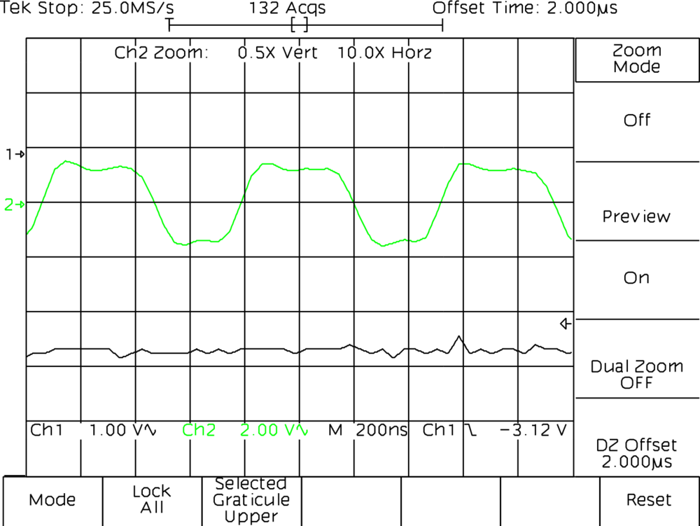
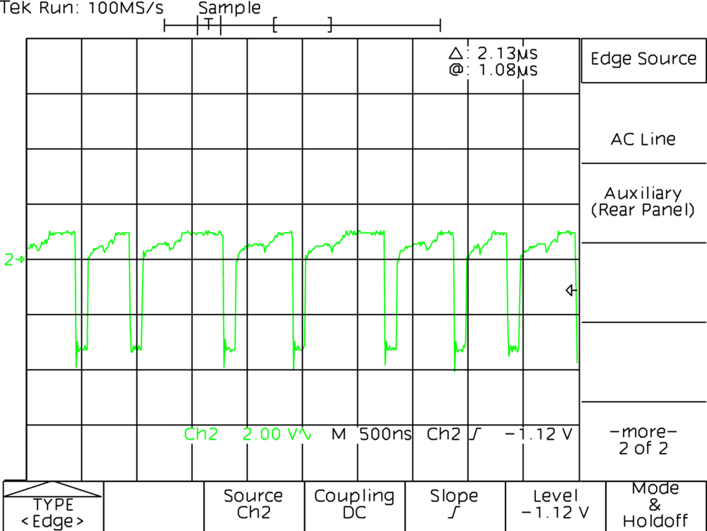
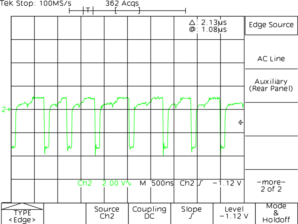
Position Signal Gain Check - Action 3 (Verify heads produces sinusoidal output)
The screen dumps below show the S1 servo burst, probed from TP2 of the read/write module. This is for Action 3 of the Position Signal Gain Check distraction.
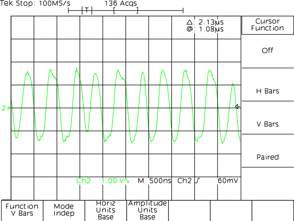
<2020-12-21 Mon 14:52> I've measured TP2 again this morning and managed to get a good capture. They look ok to me, not perfect but I feel like they should work.
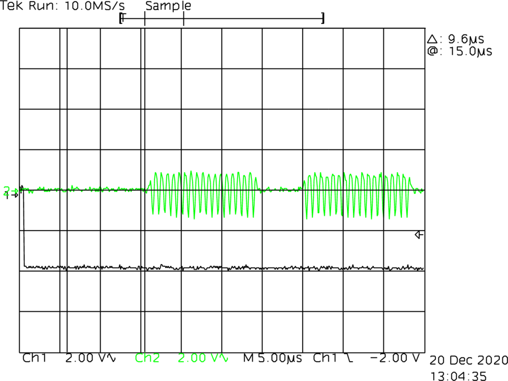
Position Signal Gain Check - Action 4 (E4 Pin 4 and Pin 9)
I refer to these screen dumps earlier, in the long section about position signal gain check. They are basically as I expected.
Tachometer signal with and without LED lighting
You can see in the middle I switched on the overhead LED lighting (which is usually on while I'm working). The noise increases quite substantially, but still, this is only 50mV or so being picked up.
Related posts:
Wanting to leave a comment?
Comments and feedback are welcome by email (aaron@nospam-aaronsplace.co.uk).